In industries ranging from pharmaceutical manufacturing to semiconductor fabrication, the quality of the controlled environment directly impacts product yield, regulatory compliance, and operational safety. Purification engineering design is the discipline that integrates mechanical systems, architectural finishes, and process controls to achieve and maintain defined cleanliness levels. Drawing on decades of project experience, TAI JIE ER has refined a set of engineering parameters that ensure robust, energy‑efficient, and compliant cleanrooms. This article examines five critical aspects of modern purification engineering design, supported by data and real‑world applications.

The foundation of any purification engineering design project is the required airborne particulate cleanliness. International Standard ISO 14644‑1 defines classes from ISO 1 (ultra‑clean) to ISO 9 (room air). For example:
ISO 5 (Class 100): Maximum 3,520 particles ≥0.5 µm/m³ – typical for aseptic filling lines and semiconductor photolithography.
ISO 7 (Class 10,000): Maximum 352,000 particles ≥0.5 µm/m³ – common in pharmaceutical compounding and medical device assembly.
ISO 8 (Class 100,000): Maximum 3,520,000 particles ≥0.5 µm/m³ – used for less critical operations like packaging.
Designers must also consider viable particle control (microbial) per EU GMP Annex 1 or USP 797. The selected class dictates every downstream decision—air changes, filter efficiency, and pressurization. TAI JIE ER begins each project with a rigorous classification analysis linked to the client’s process risk assessment.
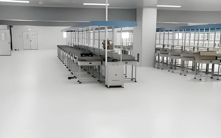
Airflow pattern is the primary mechanism for diluting and removing contaminants. Two fundamental regimes apply:
Unidirectional (laminar) flow: Used for ISO 5 and cleaner. Air moves at 0.3–0.5 m/s in a single direction (usually vertical), sweeping particles away. Ceiling coverage typically 40–80% with HEPA filters.
Non‑unidirectional (turbulent) flow: Used for ISO 6 to ISO 8. Clean air mixes with room air; the dilution rate is expressed in air changes per hour (ACH). Typical ACH values: ISO 6: 150–240; ISO 7: 30–60; ISO 8: 15–25.
Pressurization cascades prevent cross‑contamination. Cleaner areas are maintained at a higher pressure (typically 10–15 Pa) relative to adjacent less clean areas. For containment (e.g., biosafety labs), negative pressure is used. In purification engineering design, pressure differentials must be monitored with real‑time sensors and alarms.
Filtration is the core of any purification system. A typical multi‑stage setup includes:
Pre‑filters (MERV 7/8): Protect downstream components from coarse particles.
Secondary filters (MERV 13/14): Remove fine particulates before HEPA.
HEPA/ULPA filters: HEPA H14 (≥99.995% at MPPS) for ISO 5–7; ULPA U15 (≥99.9995%) for ISO 3–4.
Two common air handling architectures exist:
Central AHU with ducted HEPA terminals: Economical for large spaces; requires careful duct design to avoid leakage.
Fan‑filter units (FFUs): Modular, allowing flexible layouts and redundancy; often used in ISO 5 zones.
Energy recovery (enthalpy wheels) integrated into the AHU can reduce HVAC load by 20–30%, a key consideration in sustainable purification engineering design.
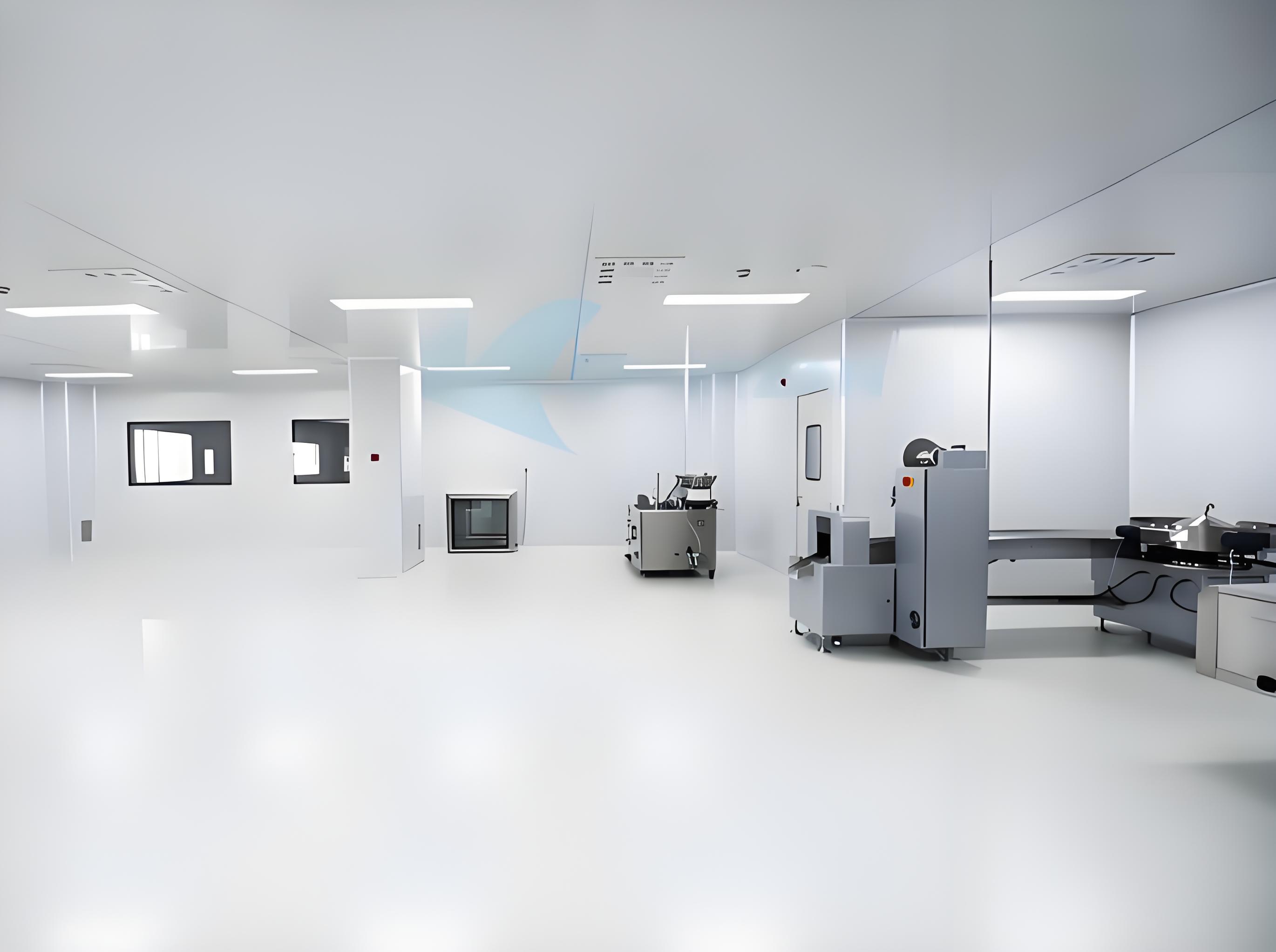
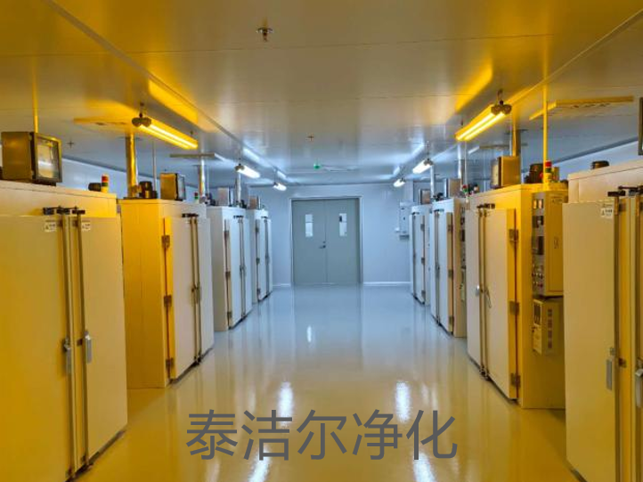
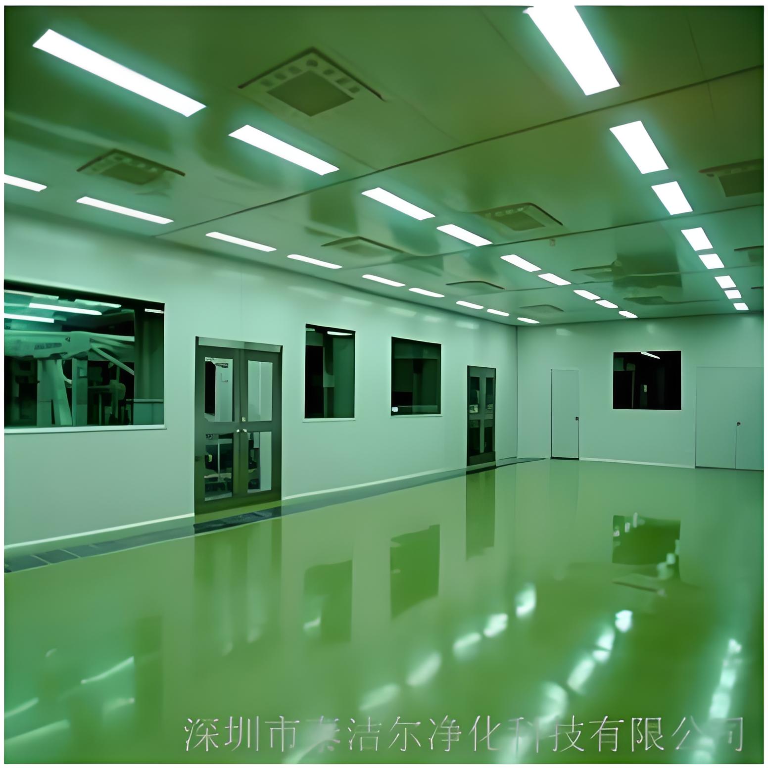
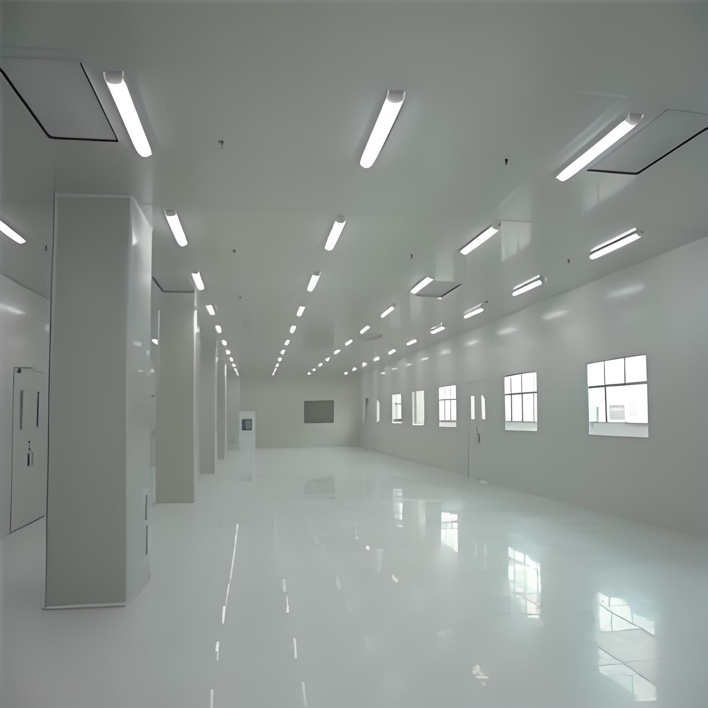
The physical envelope of a cleanroom must be non‑shedding, cleanable, and chemically resistant. Common materials:
Walls: Powder‑coated steel or aluminum honeycomb panels with baked enamel finishes; joints sealed with sanitary silicone.
Ceilings: Grid systems supporting HEPA filters and lights; gasketed to prevent bypass.
Floors: Seamless epoxy or polyurethane coatings, or welded vinyl sheet, with coved bases to eliminate corners.
Doors and windows: Flush‑mounted, with minimal ledges; interlocking for airlock sequences.
Every penetration (lights, sensors, utility feed) must be sealed to maintain room integrity. TAI JIE ER employs third‑party leak testing of the cleanroom envelope before commissioning.
Modern purification engineering design increasingly relies on smart systems for both compliance and efficiency. A building management system (BMS) with dedicated cleanroom modules can monitor:
Particle counts at critical locations (real‑time or sequential).
Differential pressure across filters and room boundaries.
Temperature and humidity (±1°C, ±5% RH typical).
Airflow velocities and damper positions.
Data logging supports regulatory audits (FDA, EMA) and enables predictive maintenance—for instance, trending filter pressure rise to schedule replacement before performance degrades. Energy optimization strategies include:
Variable‑speed drives on fans to match demand.
Demand‑controlled ventilation based on particle counts (for lower grades).
Heat recovery from exhaust air.
A purification engineering design that integrates these digital tools can reduce operational energy by 15–25% while enhancing reliability, as demonstrated in recent TAI JIE ER projects for biopharma clients.
Effective purification engineering design is a holistic discipline that balances regulatory demands, process needs, and life‑cycle cost. By meticulously addressing cleanliness classification, airflow, filtration, materials, and intelligent controls, engineers create environments that protect both product and personnel. With a track record of over 200 successful cleanroom installations, TAI JIE ER continues to advance the practice through data‑driven design and continuous innovation.
Q1: How are air change rates determined for different ISO classes in purification engineering design?
A1: Air changes per hour (ACH) are derived from ISO 14644‑4 guidelines and industry best practices. For ISO 5, unidirectional flow (0.3–0.5 m/s) equates to 240–600 ACH. For ISO 7, typical ACH is 30–60; for ISO 8, 15–25. The exact value is validated by particle count testing during commissioning.
Q2: What is the typical lifespan of HEPA filters in a cleanroom, and how is replacement decided?
A2: HEPA filters usually last 3–5 years under normal operation. Replacement is triggered by either reaching terminal pressure drop (often 2× initial resistance) or by particle count breakthrough detected during routine monitoring. Annual re‑certification (leak testing) is mandatory.
Q3: What pressure differentials should be maintained between cleanroom zones?
A3: ISO 14644‑4 recommends a minimum of 10–15 Pa between clean and less clean areas. For pharmaceutical applications, EU GMP requires ≥10 Pa differential to adjacent lower‑grade areas. In biocontainment, negative pressure (e.g., –20 Pa) is maintained relative to the corridor.
Q4: How can purification engineering design reduce energy consumption without compromising cleanliness?
A4: Key strategies include: using variable frequency drives on fans to match real‑time demand, installing energy recovery wheels, employing high‑efficiency motors, and reducing ACH during unoccupied periods (with setback modes) if risk‑assessed. TAI JIE ER has achieved 20–30% energy savings through such measures.
Q5: What are the most common pitfalls in purification engineering design for pharmaceutical facilities?
A5: Common issues include inadequate sealing of penetrations leading to bypass leakage, incorrect placement of return air grilles causing dead zones, insufficient pressurization cascades, and failure to account for heat load from equipment. Early CFD modeling and peer review help avoid these.
Q6: How does purification engineering design differ for a semiconductor fab compared to a hospital operating room?
A6: Semiconductor fabs require ISO 3–5 with strict control of airborne molecular contamination (AMC) and vibration, often using mini‑environments. Hospital ORs typically need ISO 5 (over the operating table) with unidirectional flow, plus temperature/humidity control for patient comfort and infection prevention. The design approach differs in filtration chemistry, airflow patterns, and materials.
Q7: What validation documents are required for a new cleanroom built according to a specific purification engineering design?
A7: The standard validation lifecycle includes: Design Qualification (DQ) – verifying design meets user requirements; Installation Qualification (IQ) – checking components installed per specs; Operational Qualification (OQ) – testing alarms, interlocks, and setpoints; Performance Qualification (PQ) – demonstrating sustained cleanliness over time, typically per ISO 14644‑2.
For detailed engineering assessments or to request a proposal for a custom‑engineered purification engineering design project, visit TAI JIE ER’s official website.


