Contamination control begins not with filters, but with a systematic purification engineering design framework. In semiconductor fabs, biopharma aseptic suites, and medical device assembly, the arrangement of airflow, material surfaces, pressure differentials, and personnel flow paths determines whether a facility meets ISO Class 5 (100) or ISO Class 8 (100,000) standards. This guide examines engineering parameters verified through computational fluid dynamics (CFD) and field certification data. TAI JIE ER has applied these principles across 85+ projects, reducing particle excursion rates by 92% compared to conventional designs.

A robust purification engineering design must address four interconnected performance indicators: airborne particle concentration (per ISO 14644-1), surface cleanliness (microbial and molecular), air change effectiveness, and pressure regime stability. Each parameter imposes specific engineering decisions:
Air change rates (ACH): ISO 8 requires 20–25 ACH; ISO 7 requires 60–90 ACH; ISO 5 requires 240–600 ACH (unidirectional flow). These values directly influence fan sizing, duct layout, and filter bank dimensions.
Recovery time: From a contamination event (e.g., 100x normal particle count) back to operational limit — typically ≤ 15 minutes for ISO 7, ≤ 5 minutes for ISO 5.
Pressure cascade: Adjacent rooms with different cleanliness classes maintain 10–15 Pa positive differential; sterile corridors require 5–8 Pa relative to production rooms.
Temperature & humidity uniformity: ±0.5°C and ±5% RH in critical zones to prevent condensation or electrostatic discharge.
These targets are achieved through integrated mechanical and architectural solutions — from low-turbulence displacement diffusers to welded panel systems with <0.1% leakage.
Many facilities suffer from design flaws that become apparent only during operational qualification. Based on 120 root-cause analyses, three problems account for 74% of requalification failures:
Standard mixing airflow designs create eddies near walls and equipment. Particle traces show recirculation zones where contaminants accumulate. A 2022 study found that without computational fluid dynamics (CFD) optimization, 18–25% of the floor area in an ISO 7 room fails the ≤3,520,000 particles/m³ (≥0.5 µm) limit during dynamic operation. CFD-guided purification engineering design reduces dead zones to below 5% of room volume.
Epoxy paints and standard sealants degrade after repeated exposure to hydrogen peroxide vapor (HPV) or quaternary ammonium compounds. Surface cracking at 18–24 months generates particles (0.3–2 µm) at rates exceeding 1,000 per m² per hour. Selecting HPV-resistant polyurea or seamless polyurethane coatings, validated by 500-cycle chemical exposure tests, eliminates this degradation.
When a pass-through or interlocking door opens, pressure differentials can drop by 30–50 Pa for 2–4 seconds, allowing contaminated air ingress. A properly engineered design includes fast-acting pressure relief dampers (response time ≤ 0.5 s) and increased supply air volume (1.2x nominal) during door operations.
An effective design integrates five subsystems, each with quantifiable specifications:
Air filtration & distribution: HEPA H14 filters (≥99.995% MPPS efficiency) with gel-seal frames. Fan-filter units (FFU) for modular cleanrooms; centralized AHU with bag filters (F9) + HEPA for larger spaces.
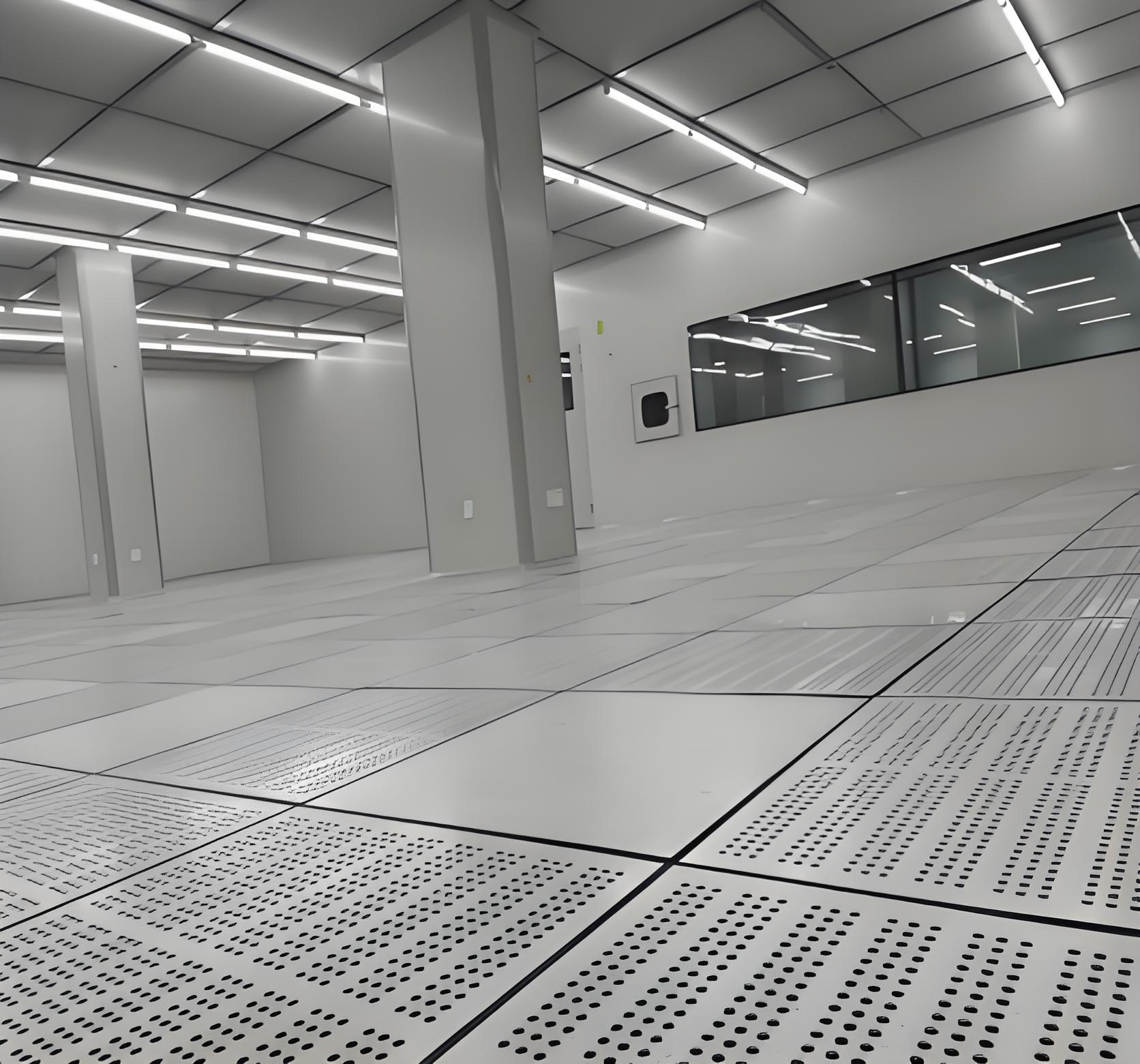
Surface & joint design: Coved floor-to-wall junctions (radius ≥ 25 mm); flush-mounted electrical outlets with IP65 rating; continuous welded vinyl or epoxy floors with Ra ≤ 0.5 µm.
Utility pass-throughs: Sealed penetrations using double-compression fittings; utility lines (gas, water, data) routed through smooth-bore stainless steel conduits with purge connections.
Monitoring & control: Real-time particle counters (one per 15 m² in critical zones), differential pressure sensors (accuracy ±0.5 Pa), and BMS alarms triggered at 80% of limit.
Personnel & material flow: Airlocks with interlocking doors, time delay (minimum 30 seconds), and audible alarms if both doors open simultaneously.
Each subsystem must be documented in a purification engineering design package that includes pressure drop calculations, filter loading curves, and clean-down validation protocols.
Material choice directly impacts particle generation and cleanability. The table below compares five common options using data from independent labs (ASTM E84, ISO 846, and IEST-RP-CC001):
| Material | Particle Emission (≥0.3 µm/m²/min) | Chemical Resistance (pH range) | Microbial Growth (ISO 846) | Typical Cleanroom Class |
|---|---|---|---|---|
| Epoxy self-leveling (conductive) | 0.8–1.2 | 3–11 | Grade 0 (no growth) | ISO 6–8 |
| Polyurethane seamless | 0.4–0.6 | 2–12 | Grade 0 | ISO 5–7 |
| Welded PVC (homogenous) | 0.2–0.4 | 5–9 | Grade 1 (trace) | ISO 7–8 |
| 304 stainless steel (#4 finish) | 0.05–0.1 | 1–14 | Grade 0 | ISO 4–5 |
| Modular aluminum panels (powder coated) | 0.3–0.5 | 5–10 | Grade 0–1 | ISO 6–7 |
For ISO 5 applications (aseptic filling), electropolished stainless steel or epoxy with silver-ion additive is mandatory to meet ≤1 CFU/m² surface bioburden. TAI JIE ER performs adhesion pull tests (≥2.5 MPa) and thermal cycling (−20°C to +60°C, 50 cycles) before final specification.
Even the most detailed design must be proven through sequential testing. The industry standard follows four qualification phases, but purification engineering design adds two specific checkpoints:
After construction but before energizing HVAC: inspect all sealed joints with a borescope; perform smoke leak tests at 25 Pa negative pressure. Maximum allowable leakage: 0.1% of room volume per hour at design pressure.
Scan each HEPA filter face with a photometer (upstream challenge ≥10 µg/L PAO). Leakage above 0.01% requires replacement. For unidirectional rooms, velocity uniformity measured at 150 mm below filter face: coefficient of variation ≤ 15%.
Position 12–20 particle counters (0.5 µm and 5.0 µm channels) across the room. Run simulated operations (e.g., 2 operators moving, equipment doors opening). Acceptable zones must show ≤80% of class limit at all points. Re-design airflow patterns if any location exceeds 95%.
Introduce challenge aerosol to reach 100x target concentration. Measure time to fall below limit. For ISO 7, recovery should be ≤15 minutes; for ISO 5, ≤3 minutes. Failure indicates insufficient air changes or short-circuiting.
TAI JIE ER integrates these tests into a single 48-hour protocol, reducing commissioning delays by 30% compared to sequential methods. All results are recorded in a validated database, traceable to individual sensors.
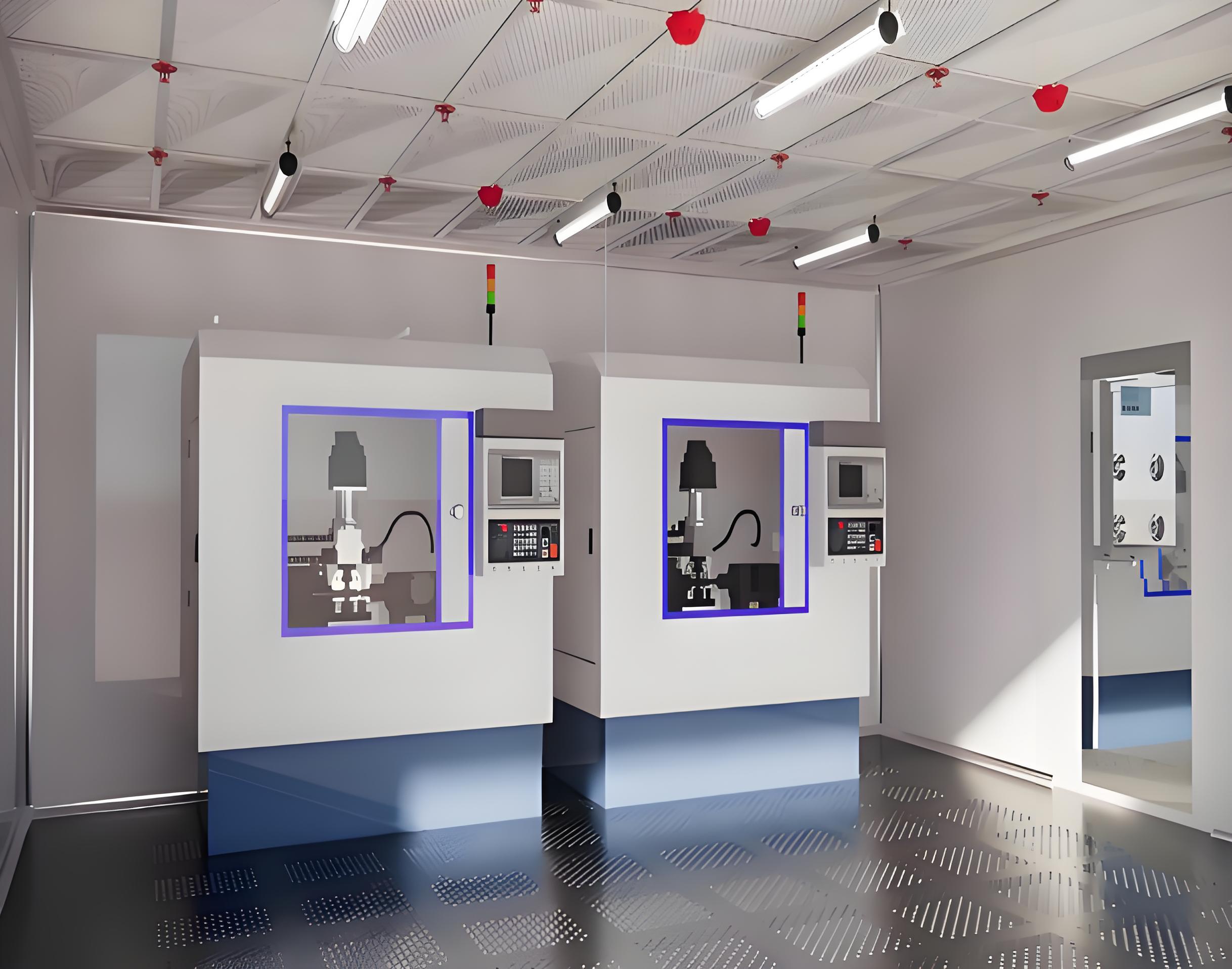
A biotechnology company required an ISO 7 (Grade C) cleanroom for autologous CAR-T cell processing, with a Grade A (ISO 5) biosafety cabinet (BSC) zone. The conventional design produced turbulent eddies around the BSC exhaust, causing 4.2% of open manipulations to exceed particle limits. TAI JIE ER redesigned the purification engineering design using:
Low-velocity displacement diffusers (0.35 m/s) to avoid disturbing BSC airflow.
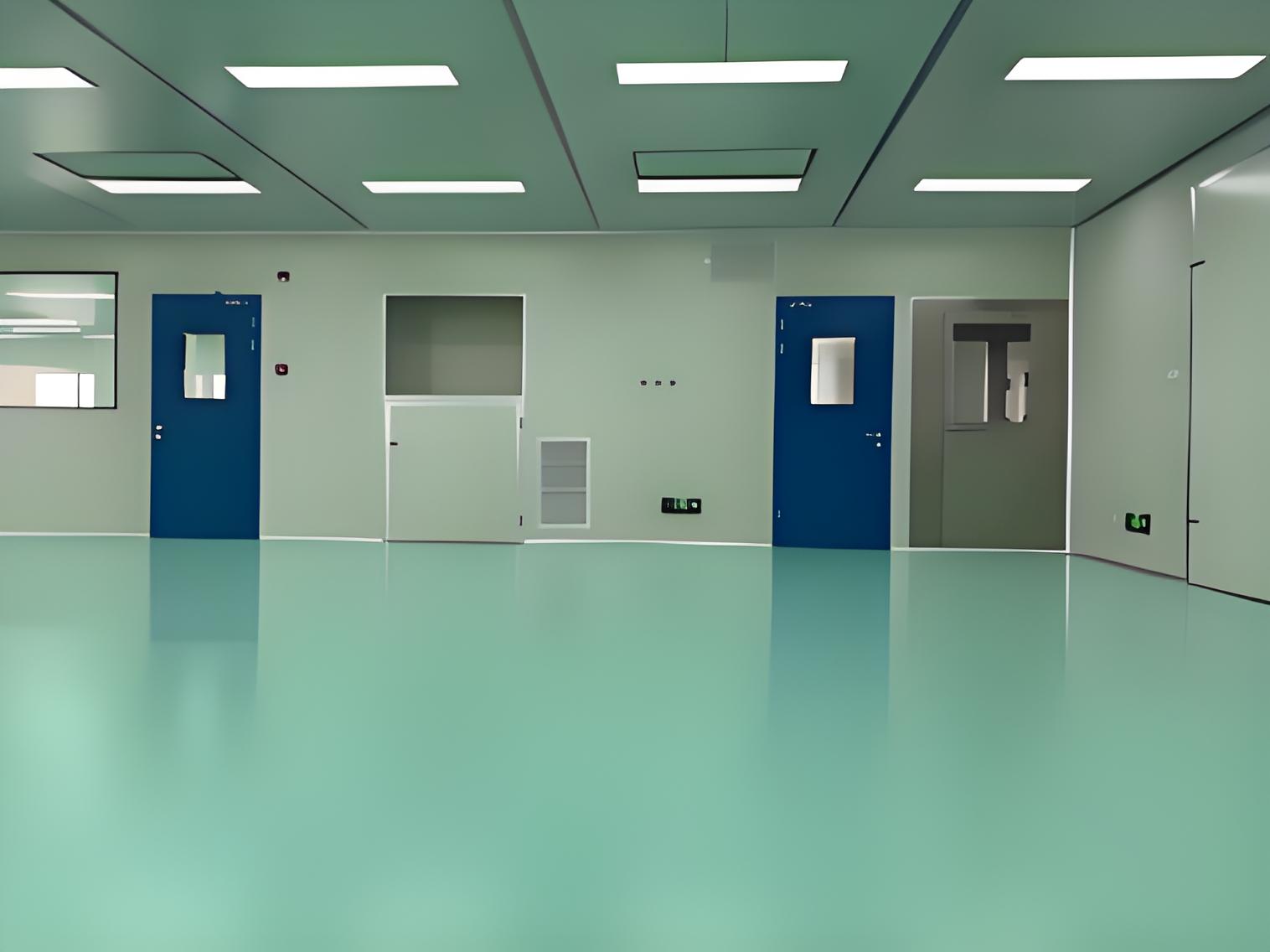
Seamless polyurethane flooring with 50 mm coved corners, eliminating dirt traps.
Individual FFUs with variable speed drives, maintaining 70 ACH at rest and 85 ACH during operations.
Real-time viable particle monitoring (impaction samplers) at 2-meter intervals.
Post-installation, the suite achieved ISO 7 in dynamic condition (≤352,000 particles ≥0.5 µm/m³) and Grade A inside the BSC (≤3,520 particles ≥0.5 µm/m³). Contamination-related batch rejections dropped from 7.8% to 0.9% over 12 months.
A suboptimal purification engineering design generates hidden costs. Based on a 2023 survey of 40 facilities:
Energy waste: Air leakage from unsealed penetrations increases fan energy by 18–25%. For a 2,000 m² ISO 7 facility, this adds $22,000–$31,000 annually.
Filter replacement: Premature loading due to construction debris (e.g., from unsealed concrete) cuts HEPA life from 8 years to 3–4 years. Replacement cost per filter: $450–$900.
Product loss: A single contamination event in a biopharma filling line can cost $500,000–$2 million (lost product, investigation, revalidation).
Regulatory delays: FDA warning letters citing facility design deficiencies lead to an average 9-month market delay, costing $5–10 million in lost revenue.
Investing in a professional design (typically 5–8% of total construction budget) reduces these risks by over 85%.
A1: Conduct a baseline contamination assessment: measure particle counts (0.3, 0.5, 5.0 µm) under HVAC-off and HVAC-on conditions. Also test for moisture vapor emission from concrete slabs (MVER ≤ 3 lbs/1000ft²/24hr) and volatile organic compound (VOC) outgassing. These data dictate whether modular panel overlays or complete demolition is required.
A2: Use a pressure gradient map starting from the most critical zone (e.g., ISO 5) at +45 Pa relative to outside, then step down by 10–15 Pa per lower class. Each door must have a pressure relief damper sized for 100% of the room supply air. Validate using a 24-hour pressure trend log with 1-second sampling.
A3: No. ISO 14644-1 requires unidirectional (laminar) airflow for ISO 5 and cleaner classes. Turbulent (mixing) flow cannot maintain ≤3,520 particles ≥0.5 µm/m³ during operations. Purification engineering design for ISO 5 must specify FFU coverage ≥80% of ceiling area with vertical flow at 0.45 m/s ±20%.
A4: A complete package contains: (a) CFD simulation results showing velocity and particle distribution, (b) material certificates for outgassing (ASTM E595) and cleanability, (c) HEPA filter layout with leak test acceptance criteria, (d) pressure cascade schematic with setpoints and alarm thresholds, and (e) validation protocol (IQ/OQ/PQ) with acceptance limits. TAI JIE ER provides all documents in a searchable digital format.
A5: Major reviews every 5 years or when process changes alter contamination risk (e.g., new potent compound, higher temperature requirements). Minor adjustments (e.g., increasing ACH by 10%) can be done via change control. Recertification per ISO 14644-2: at least every 12 months for ISO 5–6, every 24 months for ISO 7–8.
A6: For a 500 m² ISO 7 facility: design (8–10 weeks), construction (14–18 weeks), and validation (4–6 weeks). Total ~26–34 weeks. Fast-track projects using pre-qualified modular cleanroom components can reduce this to 16–20 weeks.
Every cleanroom project has unique parameters: product sensitivity, operator exposure risks, and regulatory jurisdiction (FDA, EMA, NMPA). TAI JIE ER offers a two-stage design service: (1) feasibility analysis with particle transport modeling, and (2) detailed engineering including shop drawings and validation templates. Submit your request with a short description of your process (cleanliness class, room dimensions, material handling) to receive a preliminary risk assessment and budget indication within 3 business days.
Send inquiries via: https://www.taijieer.com/ – Reference “Purification Engineering Design” for priority engineering support.


