
Precision manufacturing and biological research demand environments where airborne particles, microbial contaminants, and surface residues are systematically eliminated. Clean Workshop design is not merely about installing high-efficiency filters; it represents a holistic engineering discipline that integrates architectural planning, mechanical systems, and operational protocols. For facilities producing microelectronics, pharmaceuticals, or medical devices, the difference between a functional cleanroom and a world-class clean workshop lies in the rigor of its design philosophy.
Every effective clean workshop originates from a clear understanding of contamination sources. Particles originate from personnel (skin flakes, cosmetics, clothing fibers), equipment (moving parts, lubricants), and processes (chemical vapors, abrasion). Biological contaminants include bacteria, fungi, and endotoxins that compromise sterility. The design process begins by classifying these risks according to the product's sensitivity. A semiconductor fabrication line, for instance, tolerates no particles larger than 0.1 micrometres, while an aseptic filling suite must eliminate viable organisms entirely.
Occupants remain the predominant contamination source in occupied clean workshops. A single seated worker generates approximately 100,000 particles per minute when stationary, rising to several million during active movement. This reality forces designers to prioritize airflow patterns that sweep particles away from critical zones. Material outgassing from low-grade polymers or adhesives introduces volatile organic compounds that degrade photolithographic processes. The design must specify materials with verified low-particle shedding and chemical stability.
International Standard ISO 14644-1 establishes nine cleanliness classes based on airborne particle concentrations. A Class 5 environment (formerly Class 100) permits no more than 3,520 particles per cubic metre at sizes ≥0.5 μm, while Class 3 allows merely 352 particles at the same threshold. These classifications directly dictate ventilation rates, filter grades, and gowning requirements. Designers must select the appropriate class not as a target but as a baseline, incorporating safety margins for operational variability and filter degradation over time.
The mechanical heart of any clean workshop resides in its air handling system. High-Efficiency Particulate Air (HEPA) filters remove 99.97% of particles ≥0.3 μm, while Ultra-Low Penetration Air (ULPA) filters achieve 99.999% efficiency at 0.12 μm. The selection between HEPA and ULPA depends on the required cleanliness level and the associated energy costs. Each filter stage adds resistance to airflow, increasing fan power consumption and influencing the overall system design.
HEPA filters are typically deployed in terminal housings directly above workstations or within recirculating air handling units. ULPA filters are reserved for applications demanding ISO Class 3 or better, such as advanced lithography or gene therapy production. The filter media—typically microglass fiber or expanded PTFE—must be tested for integrity using aerosol challenge methods. Leak testing with di-octyl phthalate (DOP) or poly-alpha-olefin (PAO) aerosols verifies that the filter and its housing maintain a leak-tight seal under operating conditions.
Laminar (unidirectional) airflow moves air in parallel streams at uniform velocity, typically 0.45 m/s ± 20%, effectively sweeping particles away from the work zone. This configuration is mandatory for ISO Class 5 and cleaner environments. Turbulent (non-unidirectional) airflow uses dilution to reduce particle concentrations, suitable for ISO Class 6 through 8. The choice between these regimes impacts ceiling coverage, air change rates, and construction costs. Laminar flow systems require full ceiling plenums with perforated panels, while turbulent systems use conventional diffusers and higher air change rates—typically 20 to 60 air changes per hour versus 300 to 600 for laminar clean tunnels.
Every interior surface in a clean workshop must resist particle generation, chemical attack, and microbial colonization. The wall, floor, and ceiling systems form a continuous barrier that prevents contamination ingress from structural cavities and facilitates rigorous cleaning protocols.
Modular wall panels with smooth, non-porous surfaces—typically powder-coated steel, stainless steel, or fiber-reinforced plastic—are preferred over traditional drywall construction. Panel joints must incorporate cam-lock or tongue-and-groove connections with integral seals. Flooring systems range from seamless epoxy terrazzo to welded vinyl sheets. Epoxy floors offer chemical resistance and seamless application, while vinyl flooring provides static-dissipative properties essential for electronics assembly. The floor-to-wall cove transition eliminates right-angle joints where particulates accumulate, using preformed coving strips or site-applied sealants.
Penetrations for utilities—electrical conduits, gas lines, water pipes—represent vulnerability points. These passages must be sealed with compression gaskets, putty pads, or fire-stop systems that maintain the room's pressure integrity. All sealants must be low-outgassing and compatible with hydrogen peroxide vapor or other decontamination agents used in biopharmaceutical applications. The design specification should require that every joint withstand repeated cleaning with aggressive disinfectants without degradation.
Controlling pressure cascades prevents cross-contamination between adjacent zones. A properly designed clean workshop maintains higher pressure in cleaner areas, forcing air outward through door gaps and transfer hatches. This outward airflow acts as a dynamic barrier, preventing particle ingress from less clean corridors.
Pressure differentials of 10 to 15 Pascals between adjacent rooms are standard practice. The cascade begins at the cleanest core area (e.g., +25 Pa relative to outside) and steps down through gowning rooms, material airlocks, and corridors to the uncontrolled exterior. Each room's pressure setpoint must be maintained within ±2 Pa using variable frequency drives on supply and exhaust fans. Pressure monitoring sensors at each door or wall penetration provide continuous verification for the building management system.
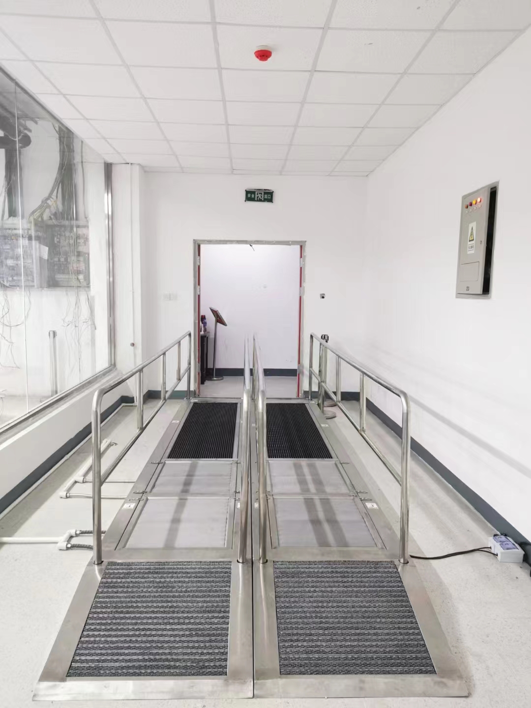
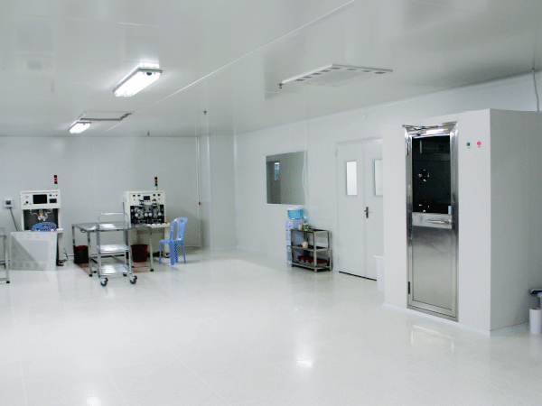
Personnel airlocks—commonly called gowning rooms—serve as transitional spaces where workers change from street clothes to cleanroom attire. The design typically incorporates three stages: outer change room (storage for personal belongings), gowning room (donning of coveralls, gloves, and masks), and final air shower or pass-through tunnel. Each stage is ventilated separately, with pressure stepping up toward the clean zone. The air shower at the final stage uses high-velocity jets to dislodge surface particles from the gown's exterior before entry.
Real-time monitoring transforms a static clean workshop into an adaptive environment. Continuous particle counting, temperature and humidity logging, and differential pressure recording provide the data necessary for operational decision-making and regulatory compliance.
Remote particle counters installed at strategic locations—near process tools, at return air grilles, and in the room's center—provide continuous data streams. These instruments use light-scattering technology to detect and size particles, with sample flow rates ranging from 0.1 to 2.83 liters per minute. Alarm thresholds alert operators to excursions, triggering investigations and corrective actions. The monitoring system must include redundant sensors and backup power to maintain surveillance during utility interruptions.
Semiconductor photolithography demands temperature stability within ±0.1 °C and relative humidity within ±1%, as thermal expansion and moisture absorption alter mask alignment and resist performance. Biopharmaceutical operations require similar precision to prevent protein denaturation and microbial growth. The HVAC system must incorporate precision cooling coils, steam humidification, and dehumidification systems with rapid response capabilities. Placing sensors in representative locations—avoiding direct airflow and heat sources—ensures accurate representative readings.
The introduction of raw materials, components, and finished products into the clean workshop must occur without compromising environmental integrity. Transfer systems range from simple pass-through hatches to sophisticated robotic transport mechanisms.
Physical separation between inbound (dirty) and outbound (clean) material flows prevents cross-contamination. Inbound materials enter through decontamination chambers or airlocks where outer packaging is removed and surfaces are wiped with appropriate solvents. Outbound materials exit through separate hatches equipped with interlocking doors that prevent simultaneous opening—an essential feature for maintaining pressure differentials. The design should clearly demarcate material staging zones with visual indicators (e.g., colored floor markings) that guide operators through established protocols.
Pass-through hatches with interlocking doors are the most common solution for small to medium-sized items. These hatches incorporate HEPA-filtered air sweeps that purge the chamber before each transfer. Larger equipment moves through dedicated material airlocks with roll-up doors and personnel access restrictions. Conveyor systems can transport items through tunnels with graded cleanliness zones, but these require elaborate sealing systems and periodic cleaning procedures.
Compliance with established standards provides the benchmark for design validation. ISO 14644 remains the global reference for airborne particle cleanliness, while specific industries impose additional requirements.
ISO 14644-1 classifies cleanrooms by particle concentration and specifies test methods for classification and monitoring. The standard requires that classification testing be performed in the "at-rest" state (equipment installed but personnel absent) and the "operational" state (normal activities in progress). The design must facilitate access for testing ports and provide adequate space for particle counter sampling probes. Documentation of baseline performance is mandatory, as regulatory auditors routinely review classification reports.
Good Manufacturing Practice (GMP) regulations enforced by the FDA and EMA mandate stringent environmental control for medicinal products. Annex 1 of the EU GMP guideline specifies particle and microbiological limits for sterile manufacturing, with grade A (equivalent to ISO Class 5) requiring unidirectional airflow during operations. The design must incorporate continuous monitoring of viable particles (via settle plates or active air samplers) and non-viable particles (via particle counters). Alarm systems must notify personnel immediately when action limits are exceeded, with predefined corrective actions.
Effective Clean Workshop design is the product of methodical risk assessment, precise engineering calculations, and operational foresight. Every decision—from filter grade to floor sealer—contributes to a cohesive system where contamination is controlled, not merely managed. Facilities that invest in thorough design processes achieve consistent product quality, reduced batch rejections, and smoother regulatory inspections.
Companies like TAI JIE ER specialize in translating these technical requirements into executable designs, integrating modular construction with advanced HVAC controls. Their engineering teams apply computational fluid dynamics to optimize airflow patterns and utilize building information modeling (BIM) to coordinate mechanical, electrical, and structural systems. TAI JIE ER project portfolios demonstrate how rigorous design translates into operational reliability across semiconductor, pharmaceutical, and medical device sectors.
For organizations planning new clean workshops or upgrading existing facilities, the design phase offers the greatest opportunity for long-term cost avoidance and quality assurance. Engaging engineering partners with documented expertise in your industry's specific requirements ensures that the final installation meets both current standards and future regulatory developments.
For inquiries about Clean Workshop design, engineering consultation, or project implementation, contact the professional team at TAI JIE ER to discuss your facility requirements.
A1: While both terms are often used interchangeably, a clean workshop generally refers to an industrial-scale facility designed for manufacturing or assembly processes, with dedicated zones for personnel, materials, and equipment. Conventional cleanrooms typically describe smaller, modular environments used for research or specialized operations. Clean workshops incorporate production logistics, utility distribution, and high-volume material handling within the contamination control strategy.
A2: Air change rates depend on the cleanliness classification. ISO Class 5 requires 300–600 air changes per hour (laminar flow), ISO Class 6 typically operates at 90–180, ISO Class 7 at 30–60, and ISO Class 8 at 15–30. These ranges are guidelines; specific rates are determined by process heat loads, particle generation rates, and occupancy levels. The final design should incorporate computational fluid dynamics simulations to validate airflow patterns under worst-case conditions.
A3: Wall systems commonly use modular panels with smooth surfaces—powder-coated steel, stainless steel (grades 304 or 316L), or high-pressure laminate. Flooring options include seamless epoxy terrazzo, welded vinyl sheets, and conductive rubber for electrostatic discharge control. Material selection must consider chemical resistance (to cleaning agents and process chemicals), particle shedding characteristics, and cleanability. All materials should be validated for low outgassing and compatibility with the intended decontamination methods.
A4: Pressure differentials are maintained through a balanced supply and exhaust air system. Each room or zone has independent supply and exhaust dampers controlled by variable frequency drives. Pressure sensors at each room provide feedback to the building management system, which adjusts airflow to maintain setpoints. Airlocks and vestibules act as pressure buffers between zones. A minimum differential of 10–15 Pa is standard, with higher differentials (20–30 Pa) used for critical barrier areas.
A5: Continuous monitoring typically includes non-viable particle counts (at multiple size channels), temperature, relative humidity, and differential pressure. Biopharmaceutical applications also require viable particle monitoring (microbial counts) via active or passive sampling methods. Additional parameters may include air velocity (laminar flow zones), oxygen concentration, and static charge levels depending on the product's sensitivity. Monitoring data should be logged with time stamps and accessible for review by quality assurance personnel.
A6: Filter replacement intervals are determined by pressure drop increase, which indicates loading. Filters are typically replaced when the resistance reaches 1.5 to 2 times the initial pressure drop, or as per manufacturer recommendations. In high-load environments, replacement may occur annually; in low-load, clean environments, filters can serve 3–5 years. Regular integrity testing (DOP/PAO scan testing) is performed annually or after any maintenance that disturbs the filter housing.
A7: An air shower is a chamber positioned at the personnel entry point, equipped with high-velocity nozzles that discharge filtered air at 20–30 m/s. The air blast dislodges loosely adhering particles from the cleanroom gown's surface. The dislodged particles are evacuated through exhaust grilles with HEPA filtration. Air showers typically operate for 15–30 seconds with interlocked doors that prevent exit during the cycle. While air showers are common in many industries, some standards (e.g., EU GMP) do not require them if other gowning controls are sufficient.