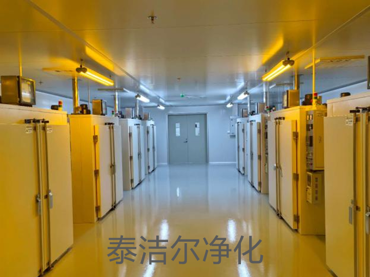
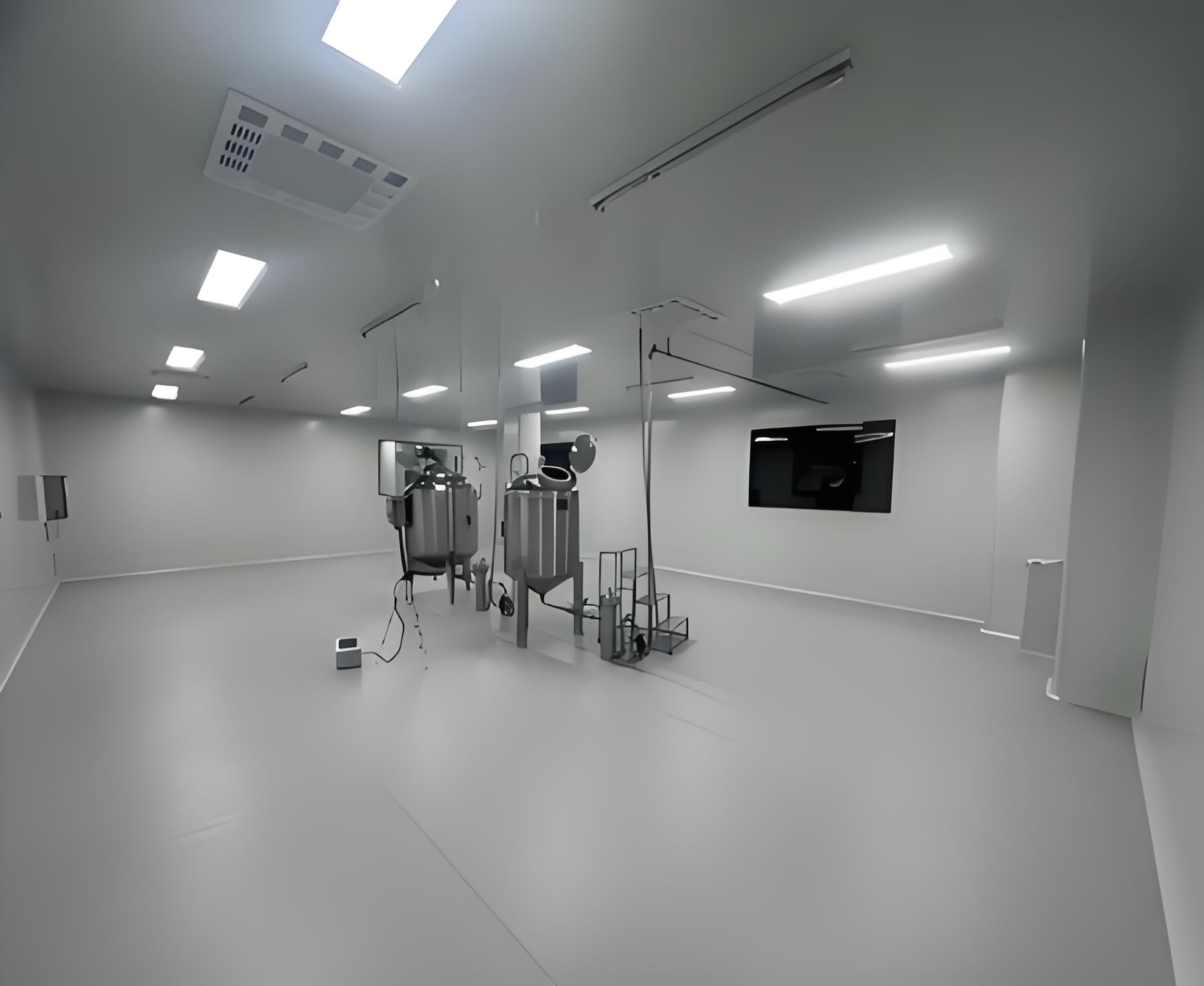
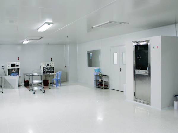
The production of pharmaceuticals, semiconductor devices, biotechnology products, and advanced optical components depends on environments where airborne particulate contamination is rigorously controlled. Cleanroom Engineering design provides the framework for constructing and operating these controlled spaces. This discipline extends beyond HVAC installation or filter selection, encompassing a systematic approach to contamination source identification, airflow physics, material compatibility, pressure relationships, and operational protocols. A properly engineered cleanroom minimizes product defects, ensures batch consistency, and maintains regulatory compliance across industries where environmental purity directly correlates with product viability.
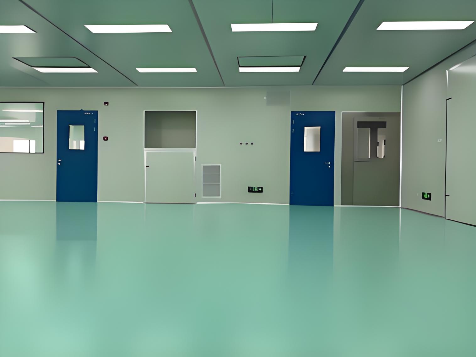
Every cleanroom engineering project begins with a fundamental question: what contaminants threaten the process, and how can they be controlled at the source? The answer determines the classification level, airflow configuration, and filtration architecture. Contamination in cleanroom environments falls into four primary categories: airborne particles, viable microorganisms, chemical vapors, and electrostatic discharge. Each category demands distinct engineering countermeasures.
Particles originate from personnel, equipment, materials, and facility infrastructure. Personnel remain the dominant contamination source in occupied cleanrooms, shedding skin flakes, hair, and fibers at rates that vary with activity level and gowning practices. Equipment generates particles through friction, vibration, and thermal cycling. Raw materials and packaging introduce particulates that become resuspended in air currents. Facility surfaces, including walls, floors, and ceiling panels, release particles through abrasion or degradation over time.
Particle distribution follows predictable aerodynamic behavior. Particles larger than 5 micrometers settle under gravitational forces, while sub-micrometer particles remain suspended and follow airflow streamlines. Intermediate particles (1 to 5 micrometers) exhibit transitional behavior, settling slowly while remaining susceptible to air current redirection. Understanding these size-dependent dynamics enables engineers to design airflow patterns that sweep particles away from critical zones rather than allowing them to deposit on product surfaces.
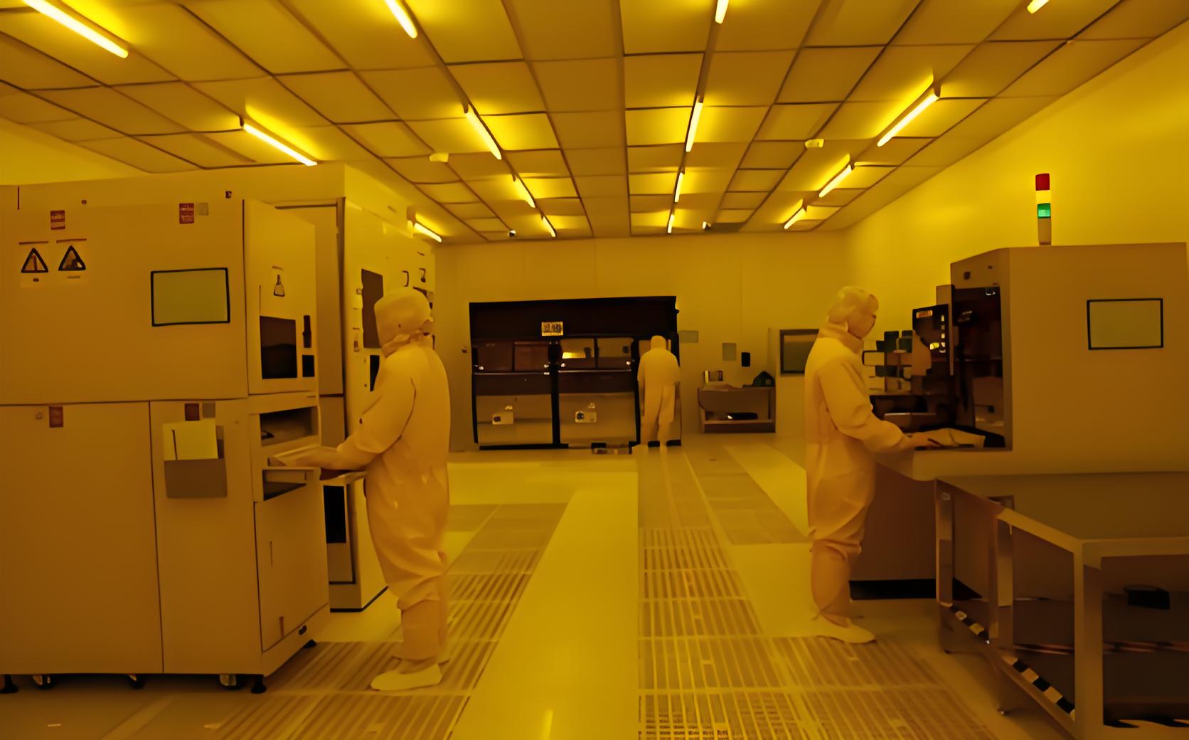
ISO 14644-1 establishes the classification framework for cleanroom environments, specifying maximum allowable particle concentrations for each class designation. ISO Class 5 permits no more than 3,520 particles per cubic meter at the 0.5-micrometer size threshold, while ISO Class 8 allows up to 3,520,000 particles at the same size. Pharmaceutical manufacturing typically operates at ISO Class 5 for aseptic processing areas, with surrounding zones graded at ISO Class 7 or 8. Semiconductor fabrication frequently requires ISO Class 3 or 4 for photolithography areas, imposing stringent filtration and airflow requirements. These classification targets drive every engineering decision, from filter bank sizing to air change rate calculations.
Airflow pattern selection represents a pivotal decision in cleanroom engineering design. The choice between unidirectional (laminar) and turbulent (non-unidirectional) flow influences particle removal efficiency, energy consumption, spatial utilization, and capital cost. This decision must align with the required cleanliness class, process characteristics, and facility constraints.
Unidirectional flow systems deliver filtered air through full-ceiling HEPA filter banks, moving air in parallel streams at consistent velocity (typically 0.3 to 0.5 meters per second). This airflow configuration displaces airborne particles from the clean zone, carrying them downward to return floor grilles. Unidirectional flow effectively removes particles introduced by personnel or activities, making it the preferred choice for ISO Class 5 and cleaner environments.
Engineering considerations for unidirectional systems include:
Filter coverage area and uniform face velocity distribution across the entire ceiling plane
Return air floor grille placement to maintain vertical airflow integrity without creating turbulence
Process equipment integration that does not obstruct airflow or create downstream wake effects
Lighting and service penetrations through the filter ceiling that do not compromise seal integrity
Operator workstations positioned to avoid disrupting airflow patterns with body movement
Unidirectional flow demands rigorous validation of velocity uniformity and airflow visualization studies to confirm that no stagnant zones or recirculation eddies exist within the working area.
Turbulent, or non-unidirectional, airflow uses ceiling-mounted filter modules that project air downward in a diffuse pattern, mixing with room air and diluting particle concentrations. This approach achieves ISO Class 7 or 8 cleanliness with lower capital expenditure and reduced energy consumption compared to unidirectional systems. Turbulent flow works effectively for packaging operations, equipment preparation areas, and materials staging zones where product exposure occurs in closed systems.
The design challenge for turbulent systems lies in achieving adequate air change rates (typically 20 to 60 air changes per hour for ISO Class 8 and ISO Class 7 respectively) while maintaining effective mixing and avoiding dead zones. Supply diffuser placement, return grille positioning, and room geometry interact to determine mixing efficiency. Computational fluid dynamics simulations assist engineers in optimizing these parameters before construction.
Pressure differentials between adjacent cleanroom zones prevent contaminant migration from less clean areas into cleaner spaces. A properly designed pressure cascade establishes a gradient from the cleanest zone outward, with each successive space at a lower pressure relative to the preceding zone. This pressure hierarchy ensures that any air leakage flows from clean to less clean areas, carrying potential contaminants away from critical processes.
Engineering a pressure cascade requires calculating supply air volumes, return air extraction rates, and leakage through doors, walls, and penetrations. The pressure differential between adjacent rooms typically ranges from 10 to 15 Pascals, sufficient to prevent reverse airflow during door openings while remaining manageable for door operation and HVAC equipment. Pressure monitoring points must be strategically located to detect deviations that signal filter loading, door seal degradation, or system imbalance.
Pressure relationships become particularly complex in facilities with multiple cleanroom grades and intervening gowning areas. Each transition zone must step down pressure incrementally, avoiding abrupt changes that could cause turbulence or door operation difficulties. Interlock systems on airlocks maintain pressure integrity during personnel and materials transfers, ensuring that both doors do not open simultaneously.
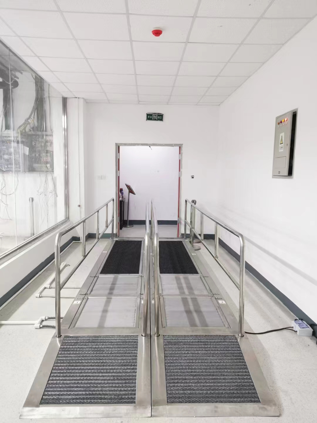
Airlocks serve as pressure barriers between cleanroom zones, providing a controlled transition space where personnel gown, materials are decontaminated, and pressure equalization occurs. The airlock design must accommodate the required throughput of personnel and materials while maintaining pressure differentials and minimizing contamination ingress. Buffer zones, or anterooms, provide additional separation between classified areas and uncontrolled spaces, offering a location for cleaning, packaging removal, and intermediate staging.
Engineering considerations for airlocks include door size and swing direction, air change rates within the airlock volume, interlocking mechanisms, and alarm systems for pressure deviations. The airlock floor plan should minimize turbulence from door-induced air movement and provide clear pathways that separate incoming from outgoing traffic flows.
Cleanroom surfaces interact continuously with the controlled environment, potentially generating particles, harboring microbial growth, or releasing volatile compounds. Material selection must consider cleanability, durability, chemical resistance, electrostatic properties, and compatibility with cleaning agents and sterilization methods. Surface finish and joint construction determine the ability to maintain a contaminant-free environment over the facility lifecycle.
TAI JIE ER provides engineering consultation for material selection, evaluating surface performance characteristics against process requirements and regulatory expectations.
Cleanroom wall panels typically consist of metal-faced sandwich panels with mineral wool or honeycomb cores, providing structural integrity, insulation, and smooth cleanable surfaces. Panel joints must be sealed with compatible sealants that resist degradation from cleaning chemicals and maintain adhesion over thermal cycling. Corner designs should eliminate crevices where contaminants accumulate, using coved transitions at floor-wall junctions and seamless intersections between panels.
Flooring systems require resistance to traffic, chemical spills, and cleaning regimens while maintaining a static-dissipative characteristic where required. Epoxy, polyurethane, and vinyl flooring options differ in durability, chemical resistance, and installation requirements. Welded seams or seamless monolithic applications prevent moisture penetration and bacterial colonization at joints.
Ceiling systems support HEPA filter housings, lighting fixtures, and service penetrations while maintaining a cleanable surface. Grid systems with gasketed filter inserts allow filter replacement without compromising surrounding seals. Ceiling penetrations for sprinkler heads, monitors, or utility drops require boot seals that prevent particle shedding and maintain pressure integrity.
Surface coatings influence both cleanability and contamination potential. Powder-coated finishes provide durable, chemically resistant surfaces with minimal outgassing. Electropolished stainless steel offers superior cleanability for pharmaceutical and biotech applications, while anodized aluminum provides lightweight corrosion resistance for semiconductor cleanrooms. Coating selection must align with the cleaning agents used in the facility, avoiding materials that degrade or become brittle upon repeated exposure.
Surface roughness deserves careful consideration. While smooth surfaces clean more readily, excessively smooth surfaces may reduce the effectiveness of cleaning agents. A balanced surface profile, typically achieved through controlled manufacturing processes, facilitates cleaning without harboring contaminants in microscopic crevices.
A cleanroom engineering design only delivers value when validated and continuously monitored. The validation process confirms that the installed system meets design specifications and achieves the required cleanliness classification. Monitoring provides ongoing assurance that environmental conditions remain within control limits throughout production operations. This validation and monitoring framework forms the basis for regulatory compliance and product quality assurance.
Cleanroom Engineering design incorporates validation protocols from the initial planning stages, ensuring that testing access ports, monitoring points, and data acquisition systems are integrated into the facility infrastructure.
Performance qualification demonstrates that the cleanroom operates within specified parameters under simulated operating conditions. Testing includes airborne particle counts at defined locations, airflow velocity measurements, air change rate verification, pressure differential assessments, filter integrity testing, temperature and humidity mapping, and recovery testing following contamination challenges. Each test follows established protocols with defined acceptance criteria, sampling locations, and measurement procedures.
Particle count testing requires selecting sample points that represent critical process zones, operator workstations, and areas of potential contamination. Sample volume and duration must provide statistically significant data while avoiding interference with operations. Filter integrity testing, typically conducted using photometer or particle counter methods, confirms that HEPA and ULPA filters maintain their rated efficiency without leakage through filter media, frames, or seals.
Continuous monitoring provides real-time data on cleanroom conditions, enabling immediate response to deviations and trend analysis for predictive maintenance. Monitoring systems typically include particle counters, pressure sensors, temperature and humidity transmitters, and airflow velocity sensors. Data acquisition systems log measurements at defined intervals, generating alerts when parameters approach or exceed control limits.
Monitoring point placement should reflect risk-based considerations, focusing on areas where product exposure occurs and where contamination events would have the greatest impact. Non-viable particle monitoring and viable air sampling complement each other, providing a comprehensive view of environmental quality. Trend analysis of monitoring data helps identify equipment degradation, filter loading patterns, or operational practices that may require adjustment.
Cleanroom engineering design must adapt to the specific requirements of each industry sector. Pharmaceutical manufacturing emphasizes microbial control, sterilization compatibility, and GMP compliance. Semiconductor fabrication prioritizes particle control at sub-micrometer sizes, chemical contamination management, and vibration isolation. Biotechnology applications demand aseptic processing capability, compatibility with biological materials, and biocontainment for genetically modified organisms.
Pharmaceutical facilities require seamless surfaces that withstand repeated cleaning and disinfection protocols, often using vaporized hydrogen peroxide or peracetic acid-based agents. Material compatibility testing must confirm that construction materials, sealants, and coatings resist these aggressive chemicals without degradation or leaching. Drainage design prevents standing water accumulation, eliminating breeding grounds for microbial growth. HVAC systems for pharmaceutical cleanrooms often incorporate 100% fresh air configurations to prevent cross-contamination and maintain product safety.
Semiconductor cleanrooms operate with stringent temperature and humidity control, as photolithography processes require thermal stability to maintain critical dimension control. Chemical filtration removes acid vapors and airborne molecular contaminants that affect wafer yields. Vibration control measures isolate process equipment from building structural vibrations, ensuring precision alignment in lithography and inspection tools.
Biotechnology facilities must balance cleanroom cleanliness with biocontainment requirements, creating spaces that protect both product and personnel. Biosafety level (BSL) classifications dictate engineering controls, including directional airflow, HEPA filtered exhaust, and decontamination systems. Autoclave and pass-through systems for materials transfer must maintain pressure barriers while facilitating efficient workflow.
Even well-conceived cleanroom designs can exhibit deficiencies that compromise performance. Experienced engineers recognize these pitfalls and incorporate preventive measures. Inadequate air change rates, often driven by energy cost pressure, result in insufficient particle dilution and extended recovery times. Engineering response involves calculating required air change rates based on particle generation rates and cleanliness targets, then sizing HVAC equipment accordingly. Variable frequency drives allow the system to operate efficiently while maintaining minimum airflow requirements.
Improper differential pressure settings cause reverse airflow during door operations or allow contamination ingress through seals. Design verification should include door opening simulations that model pressure transients, with alarms activated when pressure differentials drop below thresholds. Seal materials and door gaskets should be specified for the expected lifecycle, with maintenance schedules established to inspect and replace worn components.
Inadequate materials staging and personnel flow paths introduce contamination that the cleanroom cannot remove. Engineering designs must consider traffic patterns, material transfer methods, and personnel behaviors, incorporating buffer zones, pass-through chambers, and workflow organization that minimizes contamination risk. Operator training programs reinforce proper behavioral practices, but the engineering design should anticipate human factors and provide intuitive pathways that reduce inadvertent contamination events.
Recovery capability following contamination events requires verifying that the cleanroom returns to cleanliness specification within a defined time after contamination challenges. The recovery test confirms that air change rates and airflow patterns effectively remove contaminants. Insufficient recovery performance often indicates inadequate air change rates, poor airflow distribution, or compromised room integrity requiring seal improvements or airflow modifications.
Q1: What distinguishes cleanroom engineering design from standard
HVAC design?
A1: Cleanroom engineering design integrates multiple
disciplines beyond HVAC, including contamination source analysis, airflow
visualization, pressure cascade calculations, material compatibility assessment,
and validation protocol development. Standard HVAC focuses on thermal comfort
and energy efficiency, while cleanroom design specifically addresses particulate
and microbial control to meet defined cleanliness classifications. Cleanroom
engineers apply ISO 14644 standards and GMP guidelines, using specialized
knowledge of filtration, airflow dynamics, and surface interactions that extends
beyond conventional building services engineering.
Q2: How does the choice between unidirectional and turbulent flow
affect cleanroom performance?
A2: Unidirectional flow delivers air
in parallel streams at consistent velocity, sweeping particles away from
critical zones and achieving ISO Class 5 or cleaner conditions. This
configuration offers superior particle removal but requires higher capital
investment and energy consumption. Turbulent flow relies on dilution mixing,
achieving ISO Class 7 or 8 cleanliness with lower cost and energy demand. The
selection depends on the required cleanliness class, process sensitivity, and
operational budget. Many facilities combine both approaches, using
unidirectional flow in high-risk zones and turbulent flow in supporting
areas.
Q3: What validation tests are required for a newly constructed
cleanroom?
A3: Validation encompasses particle count testing across
the cleanroom floor plan, airflow velocity measurements, air change rate
verification, pressure differential assessment, filter integrity testing
(photometer or particle counting methods), temperature and humidity mapping, and
recovery testing that measures contamination clearance time. These tests must
follow predefined protocols with documented acceptance criteria. Performance
qualification typically includes three consecutive test runs demonstrating
consistent results before the cleanroom is released for production use. The
specific test suite varies based on classification level and industry regulatory
requirements.
Q4: How should pressure differentials be maintained during personnel
and materials transfer?
A4: Airlock systems with interlocking doors
prevent simultaneous openings that would bypass the pressure gradient. Pressure
monitoring within the airlock triggers alarms if differentials fall below set
points. The airlock volume should have adequate air change rates to restore
cleanliness after door operations. Ventilation systems within the airlock
maintain pressure relationships while preventing cross-contamination. Materials
transfer may involve pass-through chambers with independent pressure zones or
decontamination systems that preserve the pressure cascade while enabling safe
material introduction.
Q5: What role does material selection play in cleanroom contamination
control?
A5: Cleanroom surfaces continuously interact with the
controlled environment, generating particles through abrasion, harboring
microbial contamination, or releasing volatile compounds. Material selection
must balance cleanability, durability, chemical resistance, electrostatic
properties, and compatibility with cleaning and sterilization regimens. Smooth,
impervious surfaces with sealed joints prevent particle retention and facilitate
cleaning. Coating technologies provide chemical resistance and reduce
outgassing. The wrong material choice leads to persistent contamination issues,
increased cleaning frequency, and elevated risk of product quality deviations,
making material selection a fundamental engineering decision.
Q6: How can existing facilities upgrade cleanroom performance without
full reconstruction?
A6: Upgrade strategies include retrofitting
high-efficiency filters, increasing air change rates through fan and motor
replacements, improving door seals and gasketing, modifying diffuser
arrangements to enhance airflow distribution, and implementing advanced
monitoring systems for rapid deviation detection. Computational fluid dynamics
modeling helps identify airflow improvements achievable with modest physical
modifications. Existing facilities can often achieve higher cleanliness classes
by optimizing operational practices and upgrading environmental monitoring
systems while reserving full reconstruction for fundamental architectural
constraints.
For detailed engineering consultations or project-specific design inquiries, reach out to the engineering division at TAI JIE ER to discuss your cleanroom requirements and receive tailored engineering solutions that align with your process needs and regulatory environment.