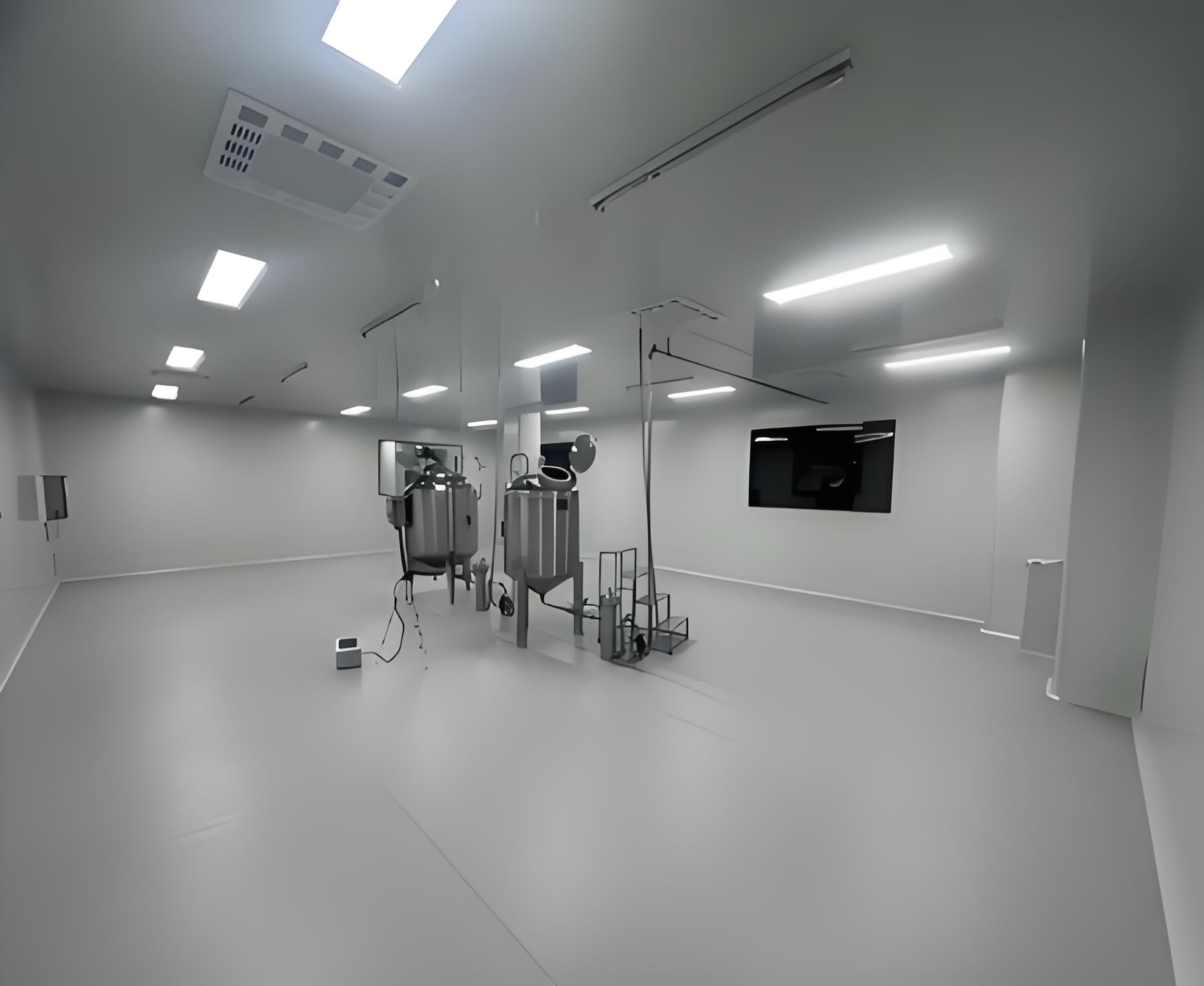
The integrity of modern manufacturing processes in semiconductor fabrication, pharmaceutical production, and biotechnology depends fundamentally on the quality of the controlled environment. Cleanroom design represents the convergence of multiple engineering disciplines: HVAC thermodynamics, particle physics, material science, and process contamination control. A properly engineered cleanroom does not merely filter air; it establishes a predictable, repeatable micro-environment where product yield, patient safety, and regulatory compliance are secured. This article examines the technical foundations, classification frameworks, and application-specific strategies that define effective cleanroom design for high-stakes industries.
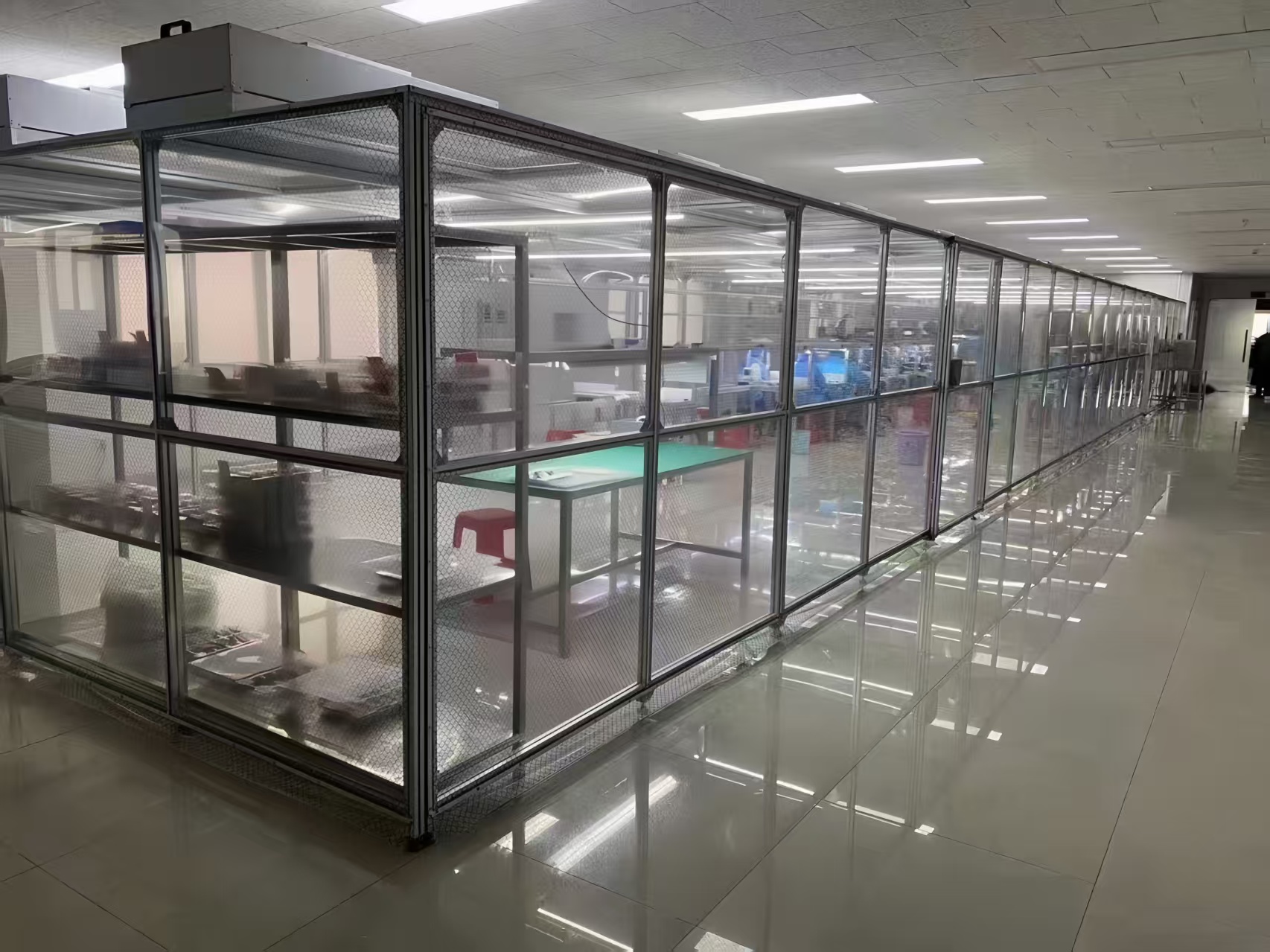
The foundation of any cleanroom design project begins with the selection of an appropriate cleanliness standard. The ISO 14644-1 classification system provides the globally accepted benchmark, defining maximum permissible particle concentrations for particles ranging from 0.1 µm to 5.0 µm. ISO Class 5, for instance, allows no more than 3,520 particles of 0.5 µm per cubic meter of air, while ISO Class 8 permits up to 3,520,000 particles at the same size threshold. These numerical limits directly influence every subsequent decision in the cleanroom design process, from airflow velocity to filter selection and room pressurization.
Pharmaceutical applications introduce additional layers of regulatory requirement. The EU GMP Annex 1 and the FDA's 21 CFR Part 11 impose operational limits that often exceed ISO classifications, particularly for aseptic processing. A Grade A zone under EU GMP corresponds roughly to ISO Class 5 in operation but requires continuous monitoring of viable and non-viable particulates, with real-time data recording. Semiconductor fabs, on the other hand, prioritize control over sub-micron particles that can cause fatal defects in photolithography, where feature sizes now measure below 5 nm. The choice between these standards shapes not only the technical specifications but also the validation protocols and ongoing monitoring strategies embedded in the cleanroom design.
Airflow architecture represents the single most consequential variable in cleanroom design. Two primary airflow regimes dominate the field: unidirectional (laminar) flow and non-unidirectional (turbulent) flow. Unidirectional flow systems move air in parallel streams at velocities typically between 0.3 and 0.5 m/s, sweeping particles away from the critical work zone. This configuration is mandatory for ISO Class 5 and cleaner environments, where even momentary turbulence can compromise sterility or particulate control. Non-unidirectional systems, suitable for ISO Class 6 through 8, rely on dilution and mixing to maintain cleanliness, using higher air change rates to compensate for the absence of directional control.
The HVAC system must deliver air change rates commensurate with the cleanliness target. ISO Class 5 environments often require 400 to 600 air changes per hour, while ISO Class 8 may operate at 15 to 30 changes per hour. These rates determine the fan energy consumption, cooling load, and filter replacement frequency. A well-executed cleanroom design accounts for heat gain from process equipment, personnel occupancy, and lighting, integrating variable frequency drives and heat recovery wheels to optimize operational efficiency. The pressure cascade, maintained at 10–15 Pa between adjacent zones of different cleanliness, ensures that contaminants from less clean areas do not migrate into critical spaces. This pressure differential must be sustained under all operating conditions, including door openings, which introduces the need for rapid-response damper systems.
Filtration selection follows directly from the required cleanliness level. HEPA filters (H13 or H14 per EN 1822) achieve 99.95% to 99.995% efficiency at the most penetrating particle size (MPPS), effectively removing particles down to 0.12 µm. ULPA filters (U15 to U17) offer even higher efficiency, up to 99.99995%, for applications requiring control over nanoparticles. The filter housing, gasket design, and installation method are critical; bypass leakage around filters can render the entire cleanroom design ineffective. Scanning tests and aerosol challenge tests verify filter integrity during commissioning and at scheduled intervals throughout the facility's operational life.
Smoke studies, conducted using non-residue-generating fog or aerosol generators, provide empirical evidence of airflow behavior under dynamic conditions. These tests are conducted at rest and in operation, with personnel performing simulated tasks, to identify areas of recirculation, dead zones, or turbulence that could compromise contamination control. Computational Fluid Dynamics (CFD) modeling is increasingly employed during the cleanroom design phase to predict airflow patterns and optimize diffuser placement before construction begins. CFD simulations can model the thermal plume from equipment, the wake effect of personnel movement, and the interaction between supply and return air grilles, enabling engineers to iteratively refine the layout without physical prototyping.
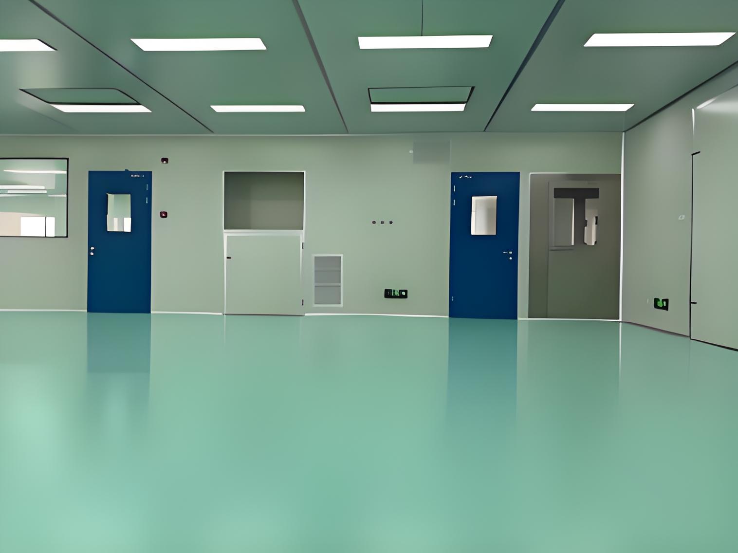
The materials used for walls, floors, ceilings, and fixtures directly influence the cleanroom's ability to resist particle generation, withstand cleaning agents, and maintain surface integrity over decades of service. Wall panels in modern cleanrooms are typically constructed from gypsum board with epoxy-painted surfaces, sandwich panels with aluminum or steel facings, or modular systems using powder-coated steel. The surface finish must be seamless, non-porous, and resistant to the chemicals used in daily sanitation routines. For pharmaceutical applications, the material must also tolerate frequent exposure to hydrogen peroxide vapor or peracetic acid, which are used for bio-decontamination cycles.
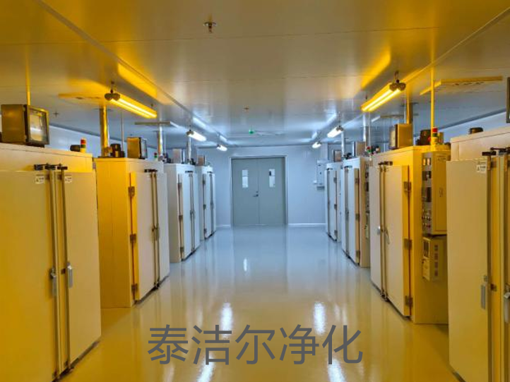
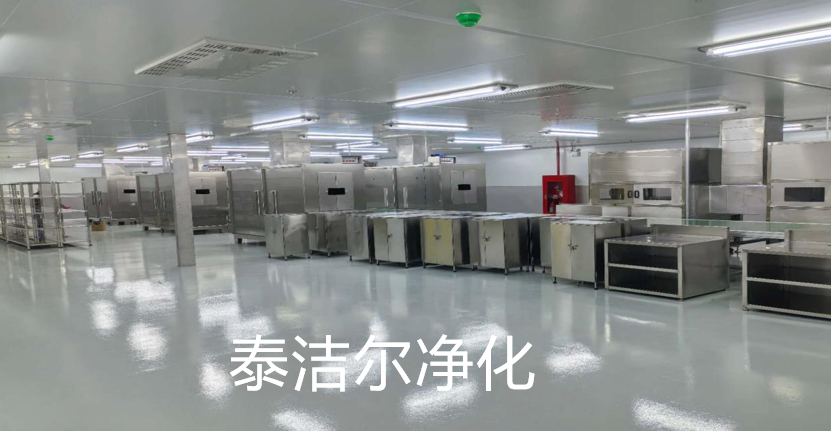
Flooring represents a particular challenge in cleanroom design. Seamless epoxy or polyurethane flooring systems are preferred for their durability, chemical resistance, and ease of cleaning. The flooring must be static-dissipative in electronics manufacturing to prevent electrostatic discharge (ESD) events that could damage sensitive components. In pharmaceutical facilities, the flooring system must include coving at the wall-floor junction to eliminate sharp corners where microbial biofilms could develop. The selection of ceiling systems—whether suspended grid with filter modules or fully sealed plenum designs—affects both the cleanroom's cleanability and its ability to accommodate future modifications to the HVAC or utility distribution.
Lighting fixtures within the cleanroom must be recessed and sealed to prevent particle accumulation on external surfaces. LED technology has largely supplanted fluorescent tubes in contemporary cleanroom design, offering improved color rendering, reduced heat load, and longer service intervals that minimize maintenance access requirements. All penetrations through the cleanroom envelope—for electrical conduits, data cables, process piping, and viewing windows—must incorporate appropriate seals to maintain the pressure differential and prevent particle ingress.
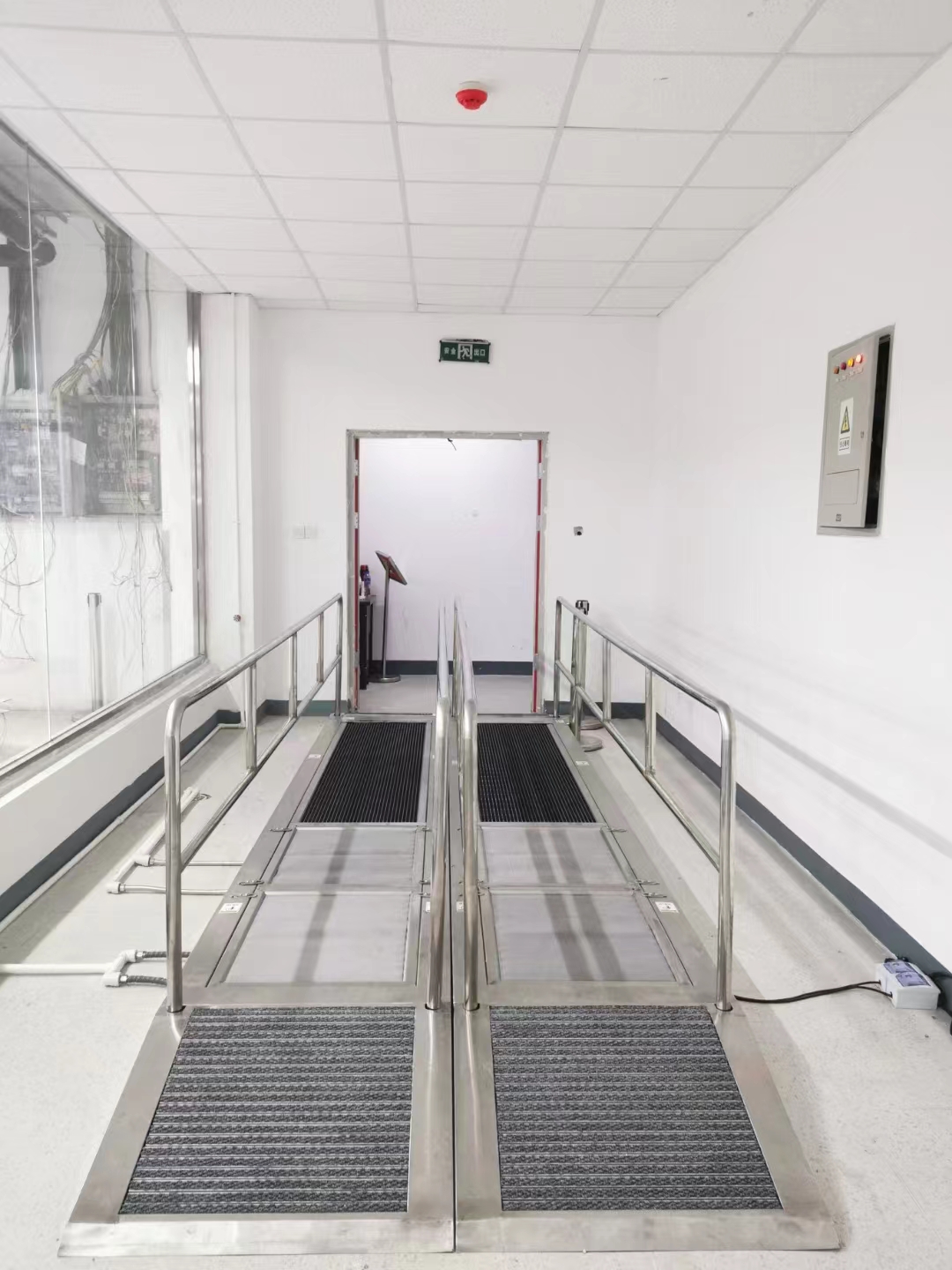
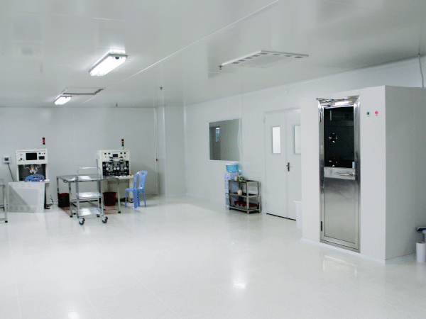
Effective contamination control extends beyond mechanical systems to encompass operational protocols, personnel behavior, and material transfer procedures. The cleanroom design must incorporate airlocks, gowning rooms, and material pass-through chambers that create a graded transition from uncontrolled environments to the cleanest zones. Personnel represent the dominant source of contamination in most cleanrooms, generating millions of particles per minute through skin shedding and movement. Proper gowning—including coveralls, hoods, booties, gloves, and face masks—reduces this emission by several orders of magnitude, but only if the gowning sequence and donning procedures are explicitly designed into the facility layout.
Material transfer strategies vary by industry and process requirements. Pass-through chambers with HEPA-filtered air showers allow materials to be introduced without compromising the cleanroom's integrity. For pharmaceutical applications, vaporized hydrogen peroxide (VHP) pass-through systems provide an additional biological decontamination step. In semiconductor fabs, automated material handling systems (AMHS) transport cassettes of wafers through sealed containers that are opened only within the cleanroom environment. Each of these solutions imposes specific spatial and utility requirements that must be integrated into the cleanroom design from the outset.
Pressure monitoring, particle counting, and environmental sensing systems form the nervous system of the cleanroom. Real-time data from these instruments informs both automated control adjustments and management decisions about process interventions. The selection and placement of monitoring points—including at critical work surfaces, return air grilles, and personnel zones—must be determined during the cleanroom design phase to ensure representative sampling without creating obstructions or contamination traps.
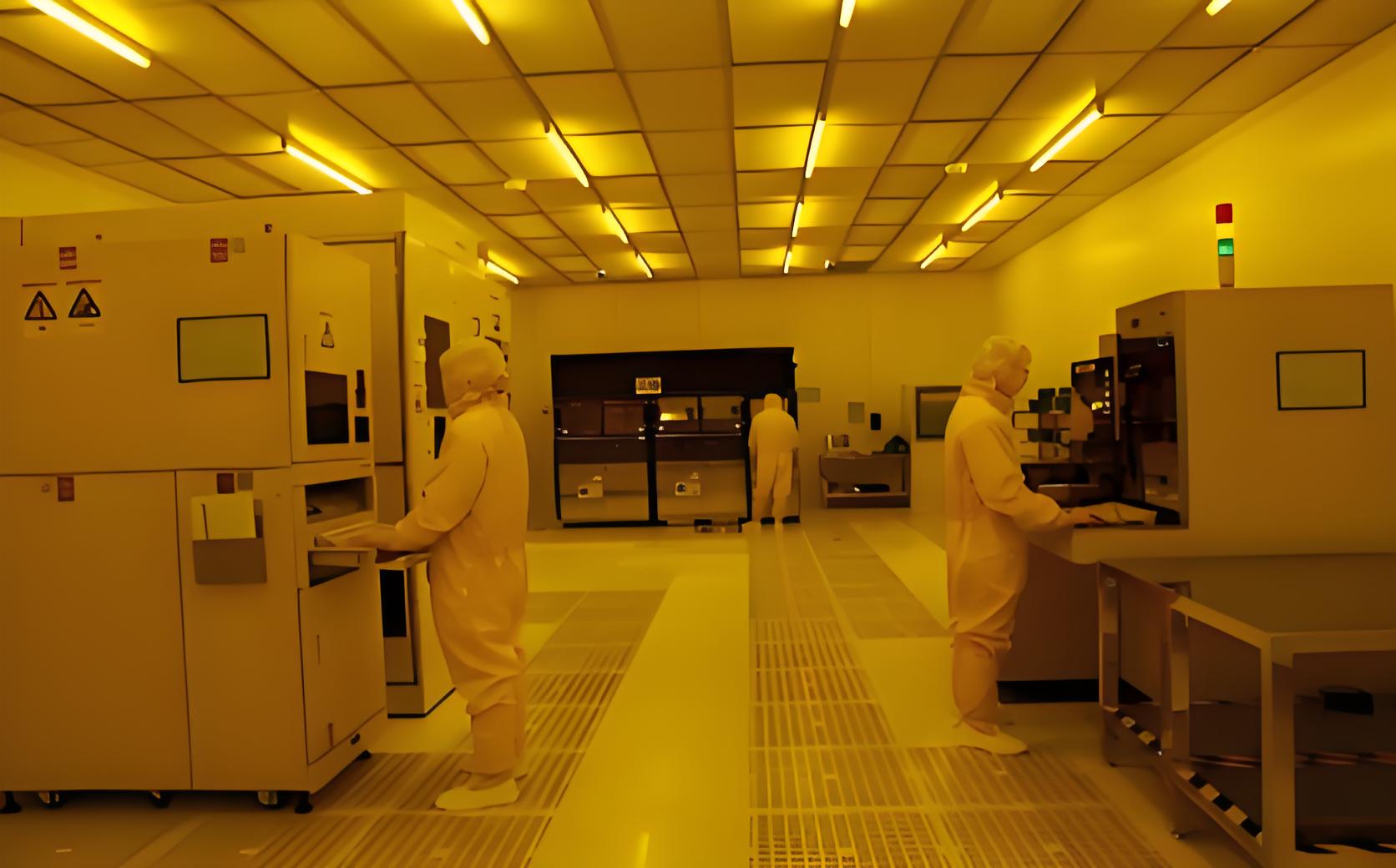
Semiconductor fabrication facilities, or fabs, operate at cleanliness levels that push the boundaries of conventional cleanroom design. With feature sizes shrinking below 5 nm, control over particles as small as 0.01 µm has become essential. This necessitates the use of ULPA filters, minienvironment enclosures around individual process tools, and advanced airflow management that maintains unidirectional flow across the entire processing bay. The cleanroom design for a 300 mm wafer fab typically encompasses ISO Class 3 or better for the main bay, with ISO Class 1 or 2 environments inside process tools and wafer handling areas.
The thermal load in semiconductor cleanrooms is substantial, with process tools generating significant heat during operation. The cleanroom design must accommodate this through strategic placement of exhaust hoods, chilled water systems, and precision temperature control that maintains ±0.5 °C stability. Vibration isolation is another critical consideration; semiconductor processes such as electron beam lithography and atomic layer deposition are sensitive to mechanical disturbances. The structural design of the cleanroom must isolate these processes from building vibrations through floating floors, vibration-damping mounts, and careful routing of mechanical services.
Chemical compatibility represents a further dimension in semiconductor cleanroom design. The use of acids, solvents, and pyrophoric gases requires integrated gas detection, emergency exhaust, and spill containment systems that do not compromise the cleanroom's particle control. Materials of construction for wet benches and chemical delivery systems must resist corrosion while maintaining smooth, non-particle-generating surfaces. The interaction between chemical processes and the cleanroom environment—particularly humidity and airborne molecular contaminants (AMCs)—must be understood and controlled through chemical filtration and environmental monitoring.
Pharmaceutical and biotechnology cleanrooms prioritize microbial control alongside particle management. The cleanroom design must support aseptic processing, where the absence of viable microorganisms is paramount. This requires not only ISO Class 5 environments for critical zones but also robust cleaning and sanitization protocols that are integrated into the facility's operational design. The use of isolator technology, where processes are enclosed within glove-port systems, reduces the reliance on room-wide cleanroom classification and allows more efficient use of space and resources.
Biotech applications, including cell and gene therapy manufacturing, introduce additional challenges related to cross-contamination between different product streams. The cleanroom design must incorporate segregation strategies that prevent cross-contact, often through physically separated suites with independent HVAC systems and dedicated personnel entry points. The single-use bioprocessing equipment trend has influenced cleanroom design by reducing the need for in-place cleaning systems, but it has also introduced new requirements for waste handling and consumable storage.
Regulatory inspection readiness is built into the cleanroom design through provisions for visual observation, sampling ports, and clear documentation of environmental monitoring data. The layout must facilitate compliance with Good Manufacturing Practice (GMP) guidelines, including clear separation of material and personnel flows, defined hold areas for in-process materials, and dedicated spaces for equipment maintenance and calibration activities.
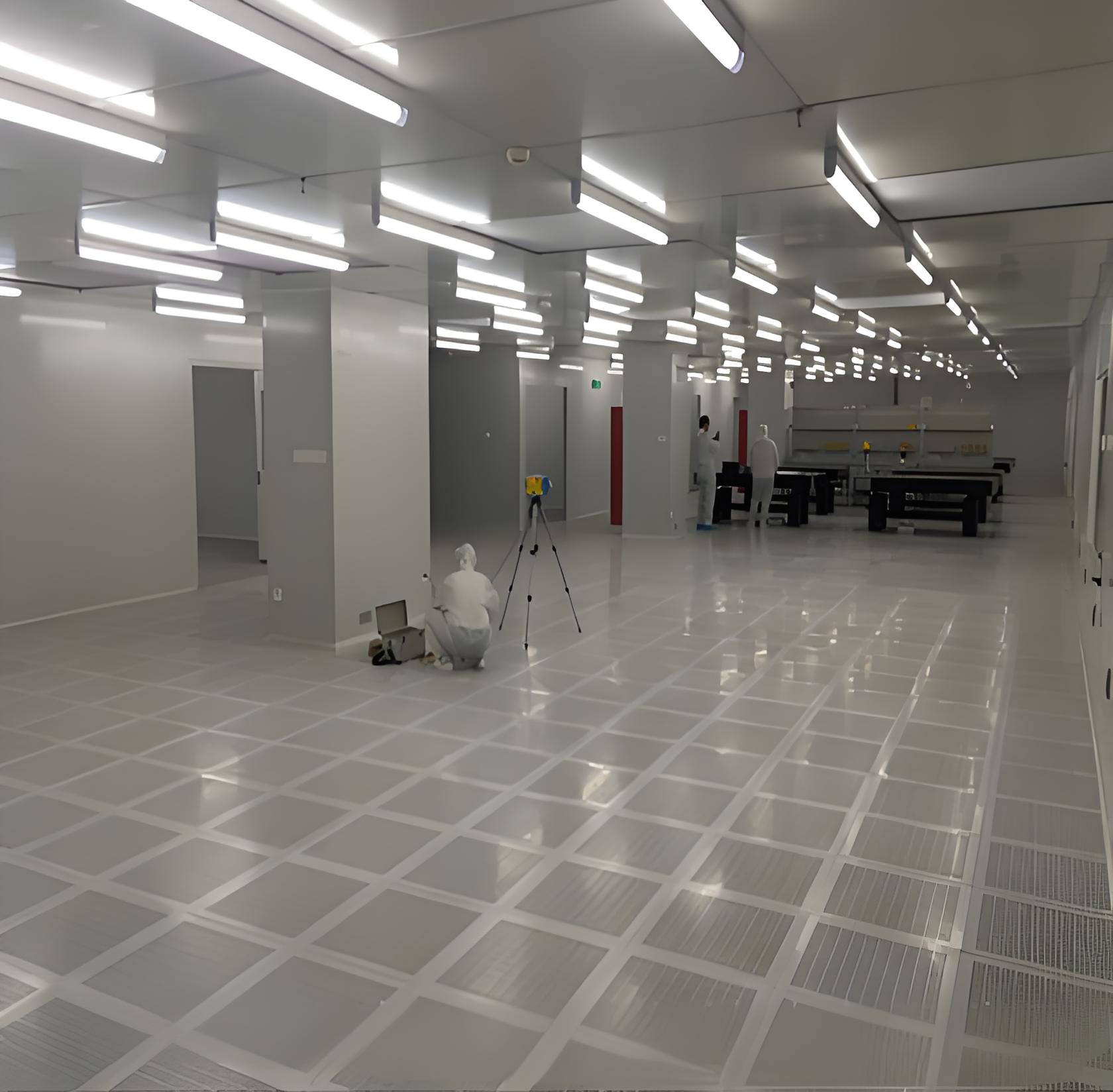
An effective cleanroom design follows a structured workflow that begins with process characterization and ends with commissioning and validation. The initial phase involves detailed documentation of the intended operations: types of materials processed, equipment layouts, personnel numbers and movements, cleaning and sanitization frequencies, and shift schedules. This operational profile informs the cleanliness classification, HVAC capacity, and spatial requirements. A concept design phase translates these requirements into preliminary layouts, airflow schematics, and material selections, often incorporating client reviews and value engineering exercises.
The detailed design phase produces construction documents, including architectural, mechanical, electrical, and plumbing (MEP) drawings, as well as specifications for all equipment and materials. Computational modeling of airflow, thermal loads, and structural loads supports the refinement of these documents. Procurement and construction follow, with quality assurance and quality control (QA/QC) measures ensuring that installations meet the design intent. The commissioning process includes performance testing of HVAC systems, filter integrity tests, airflow visualization, and particle count verification across all cleanroom zones. TAI JIE ER provides engineering consultation throughout this lifecycle, applying decades of experience in high-purity facility design to ensure that each project meets its performance targets.
Validation protocols, including operational qualification (OQ) and performance qualification (PQ), establish the cleanroom's capability to maintain specified conditions under routine operation. These protocols are typically defined in collaboration with regulatory bodies and client quality teams, ensuring that the cleanroom design is not only technically sound but also compliant with applicable standards. Documentation of all design decisions, construction records, and commissioning results forms the basis for ongoing maintenance and periodic requalification throughout the facility's operational life.
Q1: What is the difference between ISO Class 5 and ISO Class 7
cleanroom design?
A1: ISO Class 5 permits 3,520 particles of 0.5 µm
per cubic meter, while ISO Class 7 allows 352,000 particles at the same size.
This difference drives major variations in air change rates (400–600 vs. 60–90
per hour), airflow patterns (unidirectional vs. non-unidirectional), and
filtration requirements (HEPA/ULPA vs. HEPA). ISO Class 5 cleanrooms also
require stricter control over temperature and humidity, with more comprehensive
monitoring and validation protocols.
Q2: How does cleanroom design address the risk of contamination from
personnel?
A2: Personnel represent the primary contamination source
in most cleanrooms. Cleanroom design mitigates this through airlocks with
gowning areas, defined personnel flow paths, and differential pressure cascades
that prevent contaminated air from entering cleaner zones. The design also
incorporates ergonomic considerations to minimize movements that could generate
particles, and provides clear visual guidance for proper gowning and behavior
within the controlled environment.
Q3: What role does material selection play in cleanroom
design?
A3: Materials directly influence particle generation,
cleanability, and chemical resistance. Wall, floor, and ceiling surfaces must be
seamless, non-porous, and compatible with cleaning agents used in the facility.
For electronics manufacturing, materials must also be static-dissipative to
prevent ESD damage. The selection process considers durability, ease of
maintenance, and the specific chemical and thermal exposures expected during
operations.
Q4: How are pharmaceutical cleanroom design requirements different
from semiconductor cleanroom design?
A4: Pharmaceutical cleanrooms
emphasize microbial control and sterility assurance, requiring continuous
monitoring of viable particles and robust sanitization protocols. Semiconductor
cleanrooms focus on sub-micron particle control and chemical purity, with
stringent temperature and vibration tolerances. Pharmaceutical facilities must
also comply with GMP guidelines and FDA/EU regulations that mandate specific
layout and procedural requirements, while semiconductor fabs prioritize process
tool integration and contamination control at the nanoscale.
Q5: What is the importance of airflow visualization during cleanroom
design?
A5: Airflow visualization, typically through smoke studies,
provides empirical confirmation that the designed airflow patterns perform as
intended under actual operating conditions. These studies identify dead zones,
recirculation areas, and turbulence that could compromise contamination control.
The results inform final adjustments to diffuser placement, return air
locations, and operational protocols, ensuring that the cleanroom design
delivers the required performance before the facility is placed into
production.
For detailed engineering consultation and custom cleanroom design solutions tailored to your specific manufacturing requirements, please contact our technical team. TAI JIE ER offers comprehensive design, construction management, and validation services for semiconductor, pharmaceutical, and biotechnology cleanroom facilities worldwide.
Inquiries: https://www.taijieer.com/