The electronics industry operates on a microscopic scale. As printed circuit boards (PCBs) become smaller and more complex, their tolerance for contamination disappears. A single dust particle can bridge conductive pathways, causing short circuits that destroy expensive components. This is why a professionally engineered Circuit board purification project is the backbone of modern electronics manufacturing.
Manufacturers cannot rely on standard air conditioning to protect sensitive wafers and chips. They require a dedicated cleanroom environment that controls airborne particulates, static electricity, and humidity with absolute precision. Industry specialists like TAI JIE ER have spent years refining the engineering principles behind these facilities. They understand that a Circuit board purification project does not just clean the air; it secures the profitability of the entire production line.
This article examines the critical engineering standards, construction phases, and operational requirements necessary to build a world-class electronics cleanroom.
The primary goal of any Circuit board purification project is yield improvement. In the semiconductor and PCB sectors, "yield" refers to the percentage of non-defective items produced. A low yield leads to massive financial losses and wasted raw materials.
Contaminants usually attack PCBs in two ways: physical obstruction and chemical degradation. Dust particles can block light during photolithography, creating broken circuits. Alternatively, chemical vapors can settle on copper surfaces, leading to oxidation and poor solder joints later in the assembly process.
A well-executed Circuit board purification project addresses these risks by creating a sealed ecosystem. It ensures that the air touching the product is constantly filtered and that the physical environment actively repels dust.
While dust is a visible enemy, static electricity is an invisible killer. A human walking across a standard vinyl floor can generate 15,000 volts of static electricity. A microchip can be destroyed by less than 100 volts.
Therefore, an electronics-focused Circuit board purification project differs significantly from a pharmaceutical one. The engineering focus shifts heavily toward Electrostatic Discharge (ESD) control.
Key ESD control measures include:
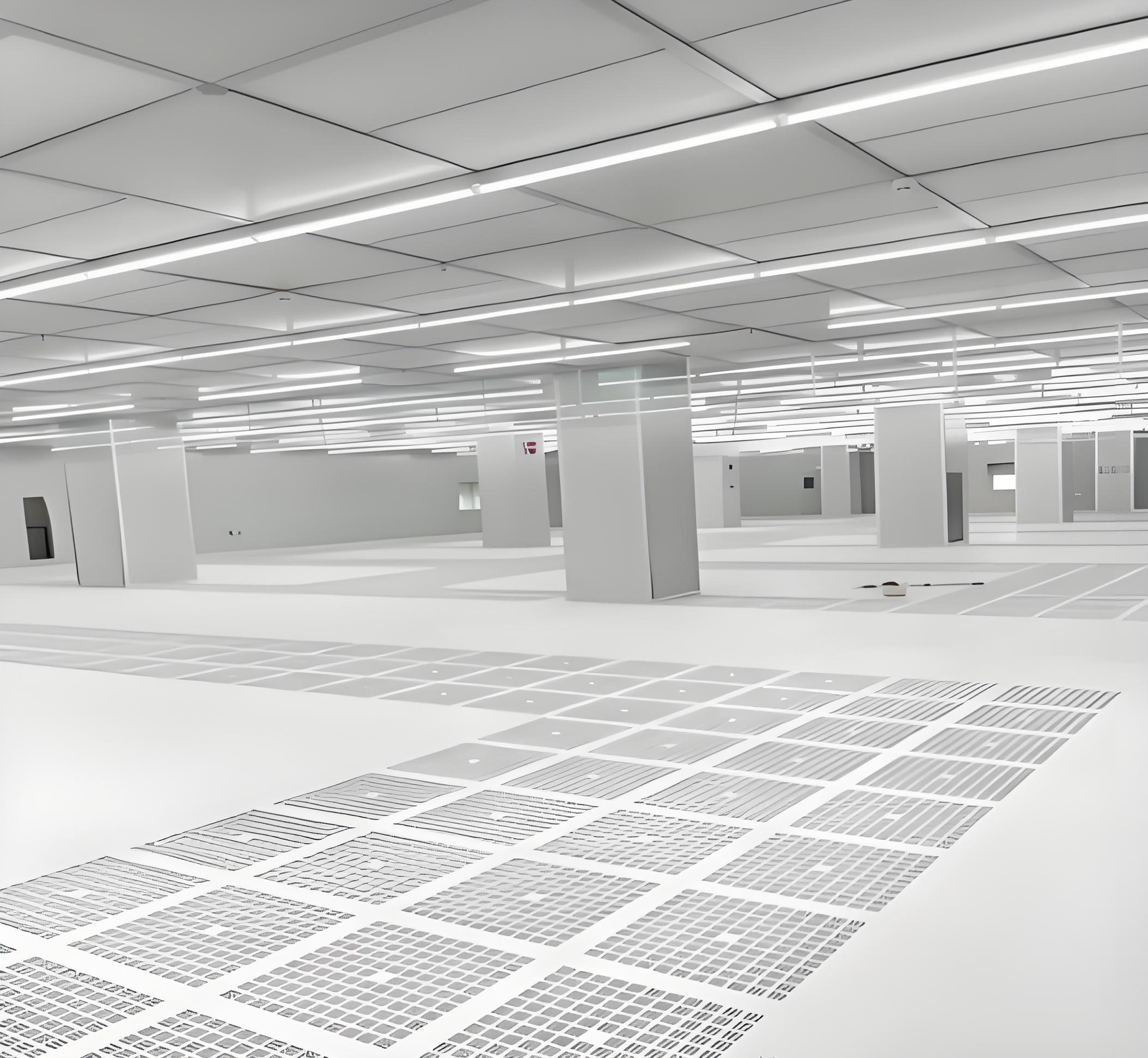
Conductive Flooring: The floor must contain a conductive grid (often copper tape) connected to an earth ground.Anti-static Wall Panels: Walls should not generate static charges when air rushes past them.Ionization Systems: Ceiling-mounted emitters release ions to neutralize static charges on insulated materials.
If a Circuit board purification project fails to integrate these systems, the room might be clean, but it will still destroy products through static shock.
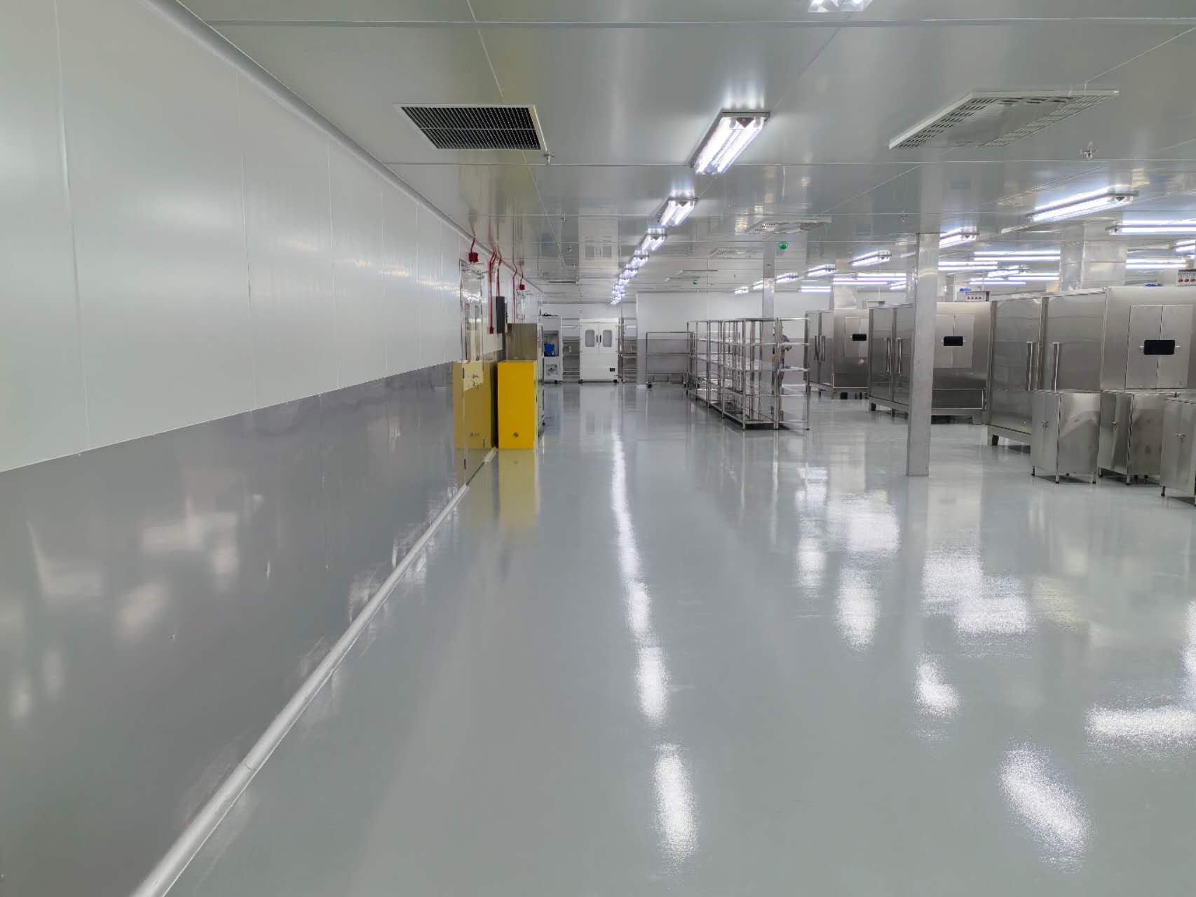
Not all cleanrooms are built the same. The level of cleanliness required depends on the specific stage of PCB manufacturing. Engineers use ISO 14644-1 standards to classify these environments.
A comprehensive Circuit board purification project often involves multiple zones with different classifications:
ISO Class 5 (Class 100): This ultra-clean zone is reserved for critical steps like exposure and photolithography. Here, laminar airflow is mandatory.ISO Class 6 (Class 1,000): Often used for wet processing and inner layer imaging.ISO Class 7 (Class 10,000): The standard for general assembly, lamination, and inspection areas.ISO Class 8 (Class 100,000): Suitable for packaging, final boxing, and support zones.
Defining these zones correctly is a major cost factor. Over-designing an entire facility to Class 5 is financially wasteful. A smart Circuit board purification project uses a "room-within-a-room" design to concentrate high-purity air only where it is strictly needed.
Electronics manufacturing materials are highly sensitive to moisture. If humidity is too high, moisture absorbs into the PCB layers. When these boards pass through high-heat reflow ovens, that trapped moisture boils and expands, causing the board to crack or delaminate—a defect known as "popcorning."
Conversely, if humidity is too low, static electricity builds up rapidly.
A successful Circuit board purification project must maintain:
Temperature: 22°C ± 2°C (for worker comfort and material stability).Relative Humidity: 50% ± 5% (to balance ESD risk and moisture absorption).
Achieving this stability requires high-precision HVAC units. Companies like TAI JIE ER often recommend desiccant wheels or reheat systems to manage moisture independent of cooling, ensuring tight tolerance control year-round.
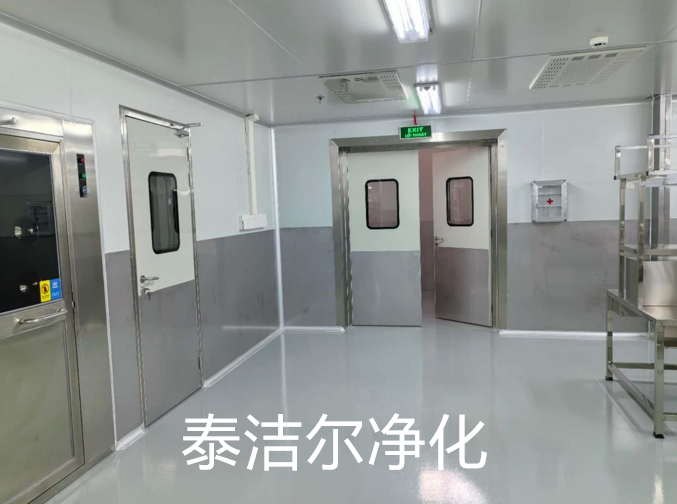
The materials used to build the cleanroom are just as important as the air handling systems. Standard drywall and wood shed particles and are strictly forbidden.
Modern construction utilizes modular sandwich panels. These panels usually feature a metal face (steel or aluminum) with a honeycomb or rock wool core. They are non-shedding, easy to clean, and anti-static.
In a Circuit board purification project, the ceiling grid must also support heavy loads. It needs to hold Fan Filter Units (FFUs) and heavy lighting fixtures. A walk-on ceiling design is often preferred, allowing maintenance crews to service lights and filters from above without entering the sterile workspace.
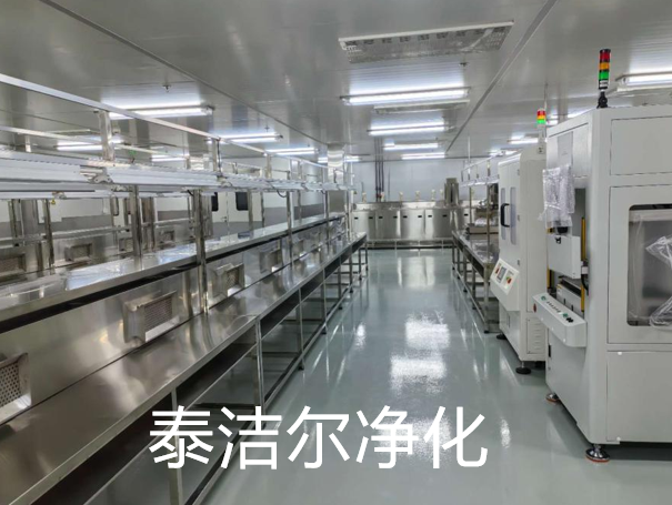
An FFU is a motorized fan attached to a HEPA filter. In older designs, a massive central air handler pushed air through ducts. Today, most electronics facilities prefer a distributed FFU system.
The benefits of FFUs in a Circuit board purification project include:
Redundancy: If one fan fails, the others continue to operate, preventing total system downtime.Flexibility: Engineers can increase the number of FFUs in a specific zone to upgrade its ISO classification later.Energy Savings: Modern DC-motor FFUs consume very little power and can be throttled up or down based on real-time sensor data.
The biggest source of contamination in any cleanroom is the people inside it. Humans shed skin cells, hair, and clothing fibers constantly.
To mitigate this, a Circuit board purification project must include strictly designed entry protocols. The layout should force personnel to pass through a specific sequence:
Shoe Change Zone: Removing street shoes to prevent tracking in outside dirt.Gowning Room: Putting on anti-static bunny suits, hoods, and masks.Air Shower: A chamber that blasts high-velocity air jets at the worker to dislodge loose particles before they enter the clean zone.
For materials, the logic is similar. Raw PCBs and components enter through "pass boxes." These are interlocking chambers that prevent air from the dirty corridor from flowing into the clean production area.
Cleanrooms are notorious energy consumers. They move massive volumes of air 24 hours a day. However, a modern Circuit board purification project incorporates smart technologies to reduce operational costs.
Variable Frequency Drives (VFDs) on air handlers allow the system to slow down when production stops at night or on weekends. Particle sensors can control fan speeds automatically. If the air is clean, the fans spin down; if particle counts rise, they speed up.
Furthermore, heat recovery systems can capture the thermal energy from exhaust air and use it to pre-condition incoming fresh air. This lowers the load on the chillers and heaters.
Building the facility is only half the battle. Verification is the final hurdle. A Circuit board purification project is not complete until it passes the validation process.
This process involves:
Airflow Velocity Testing: Ensuring air moves at the correct speed to sweep away particles.HEPA Filter Leak Testing: Checking for pinhole leaks in the filtration media.Particle Counting: Using laser counters to verify the room meets the ISO class requirements.ESD Testing: Measuring the resistance of floors and tables to ensure static charges dissipate correctly.
Third-party validation provides the documentation needed for ISO certification and customer audits.
Manufacturing high-quality electronics requires more than just advanced machinery; it demands a controlled atmosphere that eliminates variables. A Circuit board purification project provides the necessary infrastructure to maximize yield and ensure product reliability. By integrating ESD control, precise humidity management, and rigorous airflow design, manufacturers protect their sensitive components from the invisible threats of the modern world.
From the initial blueprint to the final air balance test, partnering with experienced professionals is essential. TAI JIE ER has demonstrated time and again that a detailed focus on engineering precision leads to successful project outcomes. Investing in a robust Circuit board purification project is an investment in the quality and future of your electronic products.
Q1: What is the main difference between a pharmaceutical cleanroom and a circuit board purification project?
A1: The main difference lies in the priorities of contamination control. Pharmaceutical projects focus on eliminating bacteria and living organisms (sterility). A Circuit board purification project focuses on eliminating dust particles and controlling static electricity (ESD), as static can destroy electronic components even in a sterile room.
Q2: How much space is required for the air handling equipment in these projects?
A2: You should allocate significant space for mechanical systems. Typically, the mechanical room and return air chases take up about 15% to 20% of the total floor area. Additionally, a ceiling plenum height of at least 1 to 1.5 meters is recommended to house ductwork and cabling above the cleanroom.
Q3: Can we upgrade the cleanliness level of our facility later?
A3: Yes, if the original Circuit board purification project was designed with modularity in mind. By installing a grid ceiling system capable of holding more Fan Filter Units (FFUs), you can increase the air change rate later. This allows you to upgrade a room from ISO Class 8 to ISO Class 7 without tearing down the walls.
Q4: How does a circuit board purification project handle chemical fumes from soldering?
A4: Soldering and etching processes release harmful fumes. The project design must include a dedicated local exhaust system (LEV). These are separate ducts that capture fumes directly at the source (the machine) and vent them through scrubbers before releasing them outside, ensuring the cleanroom air remains safe for workers.
Q5: How often does the cleanroom need to be recertified?
A5: ISO standards generally recommend recertification every 6 to 12 months. However, for a high-stakes Circuit board purification project, continuous monitoring systems are often installed to provide real-time data. Regular manual validation ensures that sensors are accurate and the facility remains in compliance.


