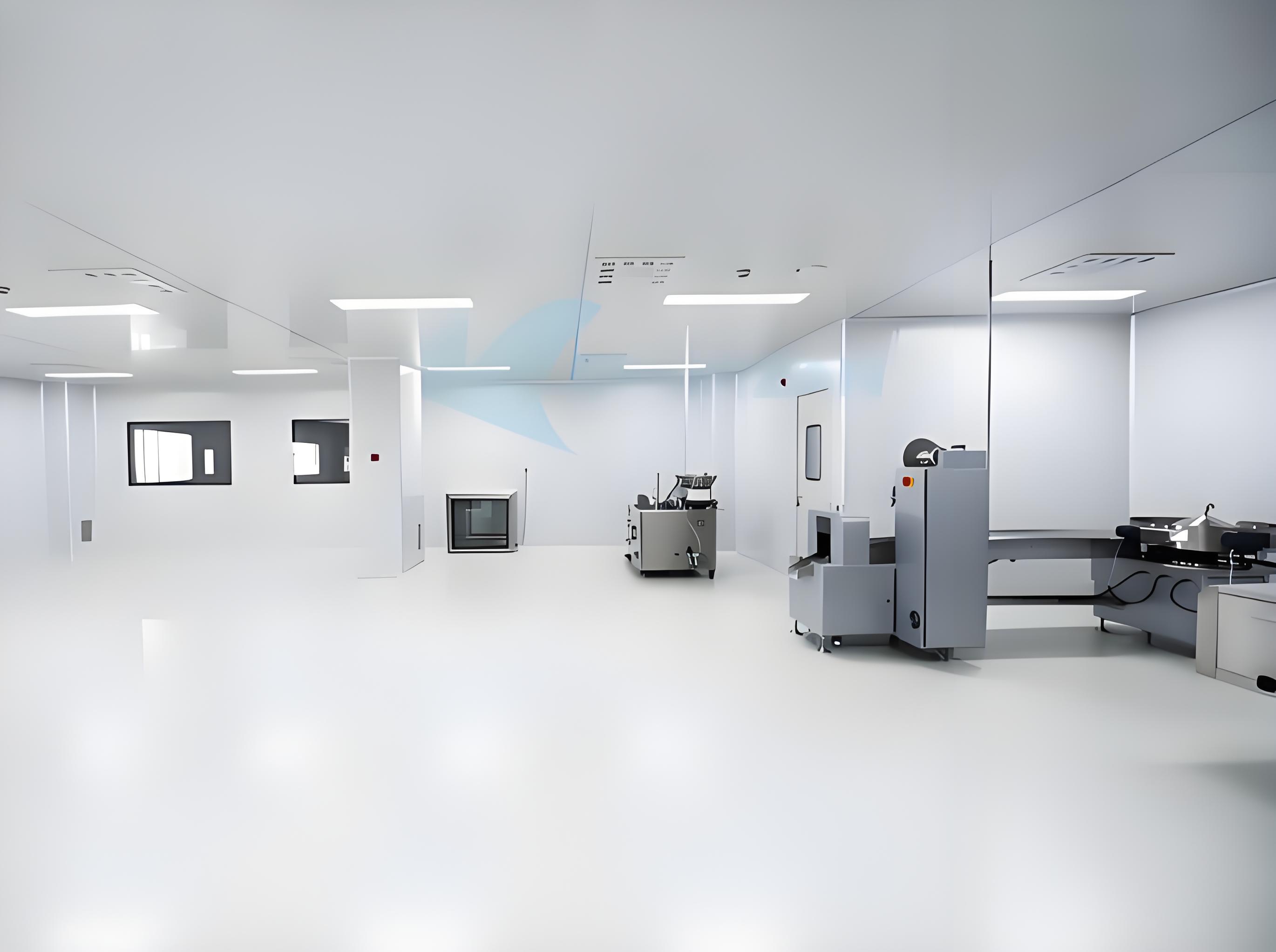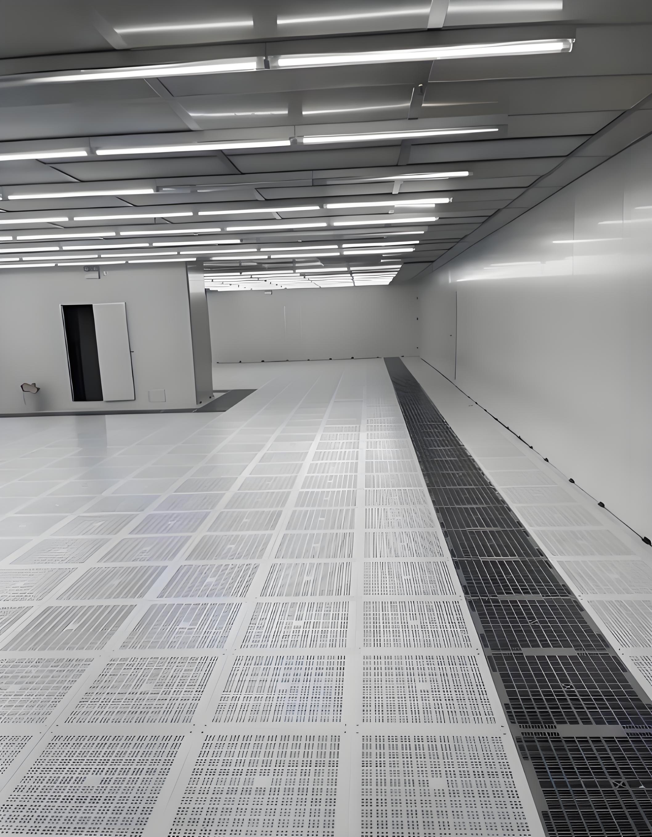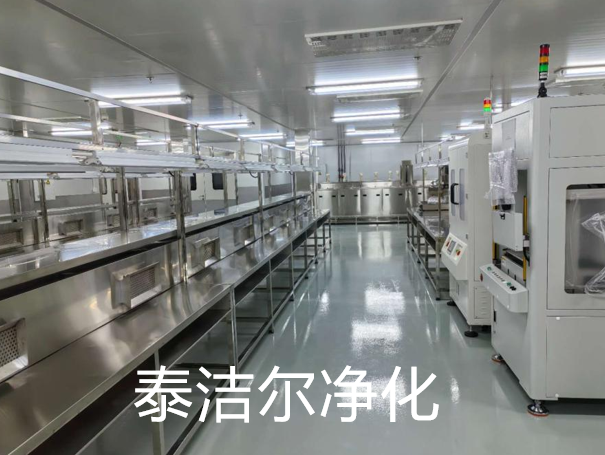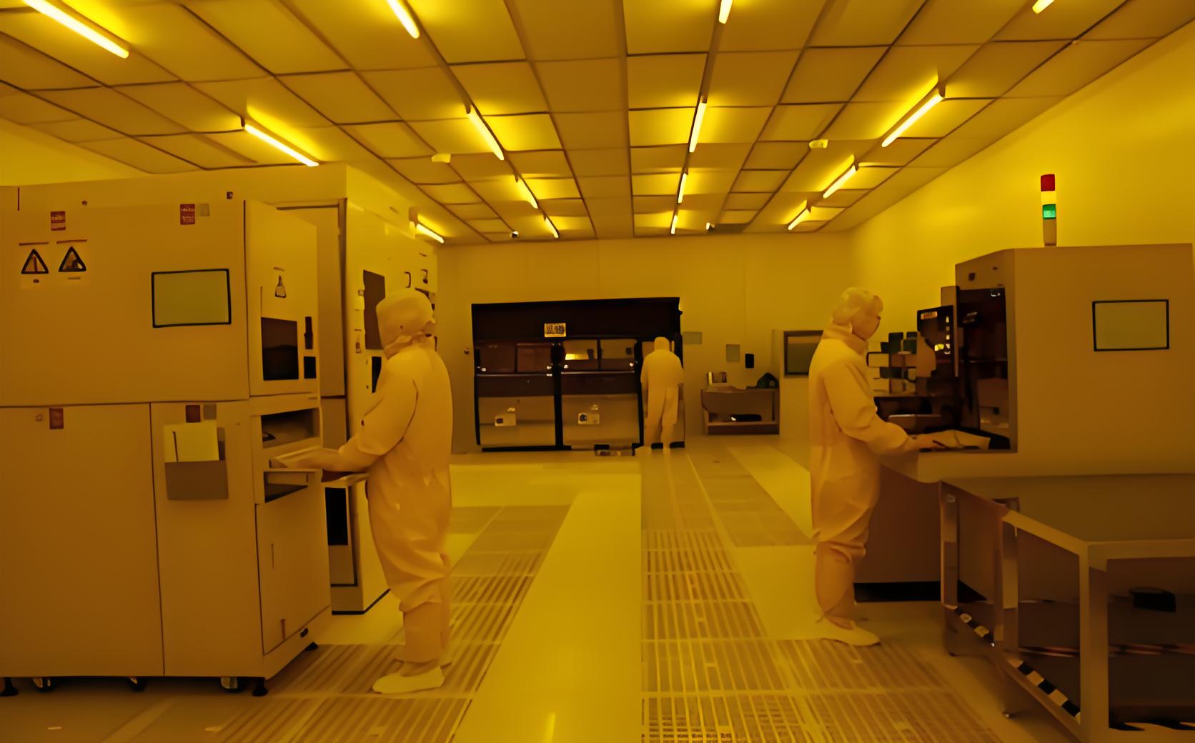
The electronics manufacturing industry continues to push boundaries in circuit density and component miniaturization. As PCB trace widths shrink to 50 µm and below, the margin for contamination-related failures narrows proportionally. A well-executed circuit board purification project addresses this challenge directly, establishing environmental controls that prevent particulate, ionic, and organic contaminants from compromising product reliability. This article provides a detailed examination of the technical framework, implementation protocols, and verification methods that define a successful purification initiative in PCB manufacturing environments.
Before designing a purification strategy, production engineers must identify the specific contaminant types present in their facility. Each category requires distinct control measures, and overlooking any source can undermine the entire circuit board purification project.
Airborne particles ranging from 0.1 µm to 100 µm originate from multiple sources:
These particles cause electrical shorts, open circuits, and intermittent failures when deposited between fine-pitch conductors or within plated through-holes.
Ionic residues—primarily chlorides, bromides, and organic acids—originate from:
These species promote electrochemical migration (ECM) and dendritic growth under bias voltage, leading to latent field failures that escape standard electrical testing.
Outgassing from adhesives, conformal coatings, and packaging materials releases volatile organic compounds (VOCs) that adsorb onto PCB surfaces. Silicone-based mold release agents, in particular, create hydrophobic films that interfere with solder wetting and wire bonding adhesion.
Establishing a baseline for cleanliness requires reference to internationally recognized standards. The following specifications form the foundation of any comprehensive circuit board purification project.
ISO 14644-1: This standard defines cleanroom classification by airborne particle concentration. For PCB assembly operations, Class 7 (ISO 7) or Class 8 (ISO 8) environments are common, though high-density interconnect (HDI) and advanced packaging facilities frequently require ISO 6 or better. The classification directly influences air change rates, filter selection, and gowning protocols.
IPC-6012: The rigid printed board qualification and performance specification includes cleanliness requirements measured by resistivity of solvent extract (ROSE) testing. IPC-6012 sets maximum ionic contamination levels at 1.56 µg NaCl equivalent per cm² for Class 2 and Class 3 boards, with tighter limits for high-reliability aerospace and medical applications.
IPC-J-STD-001: This standard addresses soldered assembly cleanliness, incorporating visual inspection criteria and surface insulation resistance (SIR) testing protocols. Compliance ensures that cleaning processes—whether aqueous, semi-aqueous, or vapor-phase—achieve adequate residue removal without damaging board materials.
These standards collectively define the target performance metrics for any purification initiative. Engineering teams must align their project scope with the applicable standards for their product class and customer requirements.
A complete purification system comprises multiple interdependent subsystems, each contributing to overall contamination control. The design phase of a circuit board purification project must balance filtration efficiency, airflow dynamics, and process compatibility.
HEPA (High-Efficiency Particulate Air) filters with minimum efficiency reporting value (MERV) 17 or higher remove 99.97% of particles 0.3 µm and larger. For applications requiring sub-0.1 µm control, ULPA (Ultra-Low Penetration Air) filters achieve 99.999% efficiency at 0.12 µm. The filter placement—ceiling-mounted fan-filter units (FFUs) versus centralized ducted systems—affects both capital expenditure and operational flexibility.
Airflow patterns deserve equal attention. Unidirectional (laminar) flow provides superior particle sweep-out compared to turbulent (non-unidirectional) flow, particularly in critical work zones. Computational fluid dynamics (CFD) modeling assists in optimizing diffuser placement, return air grille positions, and pressurization differentials between cleanliness zones.
Activated carbon and chemically impregnated media filters adsorb airborne molecular contaminants (AMCs) that bypass particulate filters. These systems target specific compounds—sulfur dioxide, ozone, and volatile organic compounds—that corrode copper traces and degrade solderability. Monitoring AMC levels with real-time gas chromatographs enables proactive filter replacement before performance degrades.
Electrostatic discharge (ESD) events attract particles to charged surfaces and can damage sensitive components. Ionization systems—either corona discharge or alpha-particle emitters—neutralize static charges on boards, fixtures, and operators. Placement of ionizing blowers at key process stations (screen printers, placement machines, and reflow ovens) prevents electrostatic attraction from offsetting the benefits of particulate filtration.
Technical infrastructure alone does not guarantee success. The purification project must integrate with existing production workflows, defining personnel behavior, material handling, and maintenance schedules.
Raw PCBs, components, and consumables enter the cleanroom through airlocks with interlocking doors. Pass-through chambers with HEPA-filtered air showers remove loose particles from incoming packaging. Staging areas within the cleanroom maintain separation between dirty and clean zones, preventing cross-contamination from secondary operations such as depaneling or edge routing.
Cleanroom garments—coveralls, hoods, booties, and gloves—form the primary barrier against human-sourced contamination. The garment material must balance particle retention with breathability to minimize operator fatigue. Gowning rooms with step-over benches and sticky mats reduce particle ingress. Regular training sessions reinforce proper donning procedures, hand hygiene, and movement patterns that minimize particle generation.
Specific production steps carry higher contamination risk and require dedicated purification measures:
Validation ensures that purification measures achieve the specified cleanliness levels. Monitoring provides ongoing assurance that performance remains within acceptable bands.
Portable and fixed-mount particle counters sample air at defined locations and frequencies. ISO 14644-1 requires sampling at multiple points per cleanroom area, with statistical analysis to determine classification compliance. Trending particle counts over time reveals filter loading, seal degradation, or process excursions before they cause product defects.
ROSE testing measures ionic contamination directly from board surfaces. Solvent extraction followed by conductivity measurement provides a quantitative result in µg NaCl equivalent per cm². For more detailed analysis, ion chromatography (IC) identifies specific ionic species—chloride, bromide, sulfate, and organic acids—enabling targeted corrective actions.
Surface insulation resistance (SIR) testing applies bias voltage to test patterns under controlled humidity and temperature, measuring leakage current over 500 to 1000 hours. SIR identifies dendritic growth susceptibility and validates that cleaning processes leave boards sufficiently residue-free for long-term reliability.
Temperature, humidity, and differential pressure sensors feed data to a building management system (BMS) or dedicated cleanroom monitoring platform. Alarms trigger when parameters deviate from setpoints, allowing rapid operator intervention. Data logs provide evidence for quality audits and root-cause analysis of yield excursions.
This continuous monitoring loop differentiates a reactive cleaning approach from a proactive purification strategy. Data-driven decisions on filter replacement, garment rotation, and process adjustments derive directly from monitored performance metrics.
Implementation of a purification project encounters recurring obstacles. Anticipating these issues accelerates deployment and improves final outcomes.
Filter bypass and seal integrity: Even small gaps in filter frames or duct connections allow unfiltered air to enter the cleanroom. Ultrasonic leak testing and aerosol challenge tests identify bypass paths. Regular inspection of gaskets and sealants maintains integrity over time.
Operator compliance: Gowning protocols and cleanroom behaviors are only effective if consistently followed. Visual management tools—checklists, signage, and color-coded zones—reinforce correct practices. Supervisory audits with documented feedback drive adherence.
Process-generated contaminants: Some production equipment inherently produces particles or fumes. Local exhaust ventilation (LEV) at the source captures emissions before they disperse into the cleanroom. For example, laser marking and depaneling stations benefit from dedicated vacuum systems with HEPA exhaust.
Moisture and humidity control: High relative humidity promotes ionic migration and corrosion, while low humidity generates static charges. Precision humidity control systems with desiccant dryers or steam injection maintain setpoint within ±5% RH, stabilizing the electrostatic environment and reducing contamination risks.
Each challenge resolution requires systematic investigation and tailored engineering solutions. TAI JIE ER brings extensive experience in diagnosing and remediating such issues across diverse PCB production lines, offering engineering support that spans from initial assessment to full-scale implementation.
Integration of these solutions transforms the circuit board purification project from a collection of equipment purchases into a cohesive, performance-driven system. The result is measurable improvement in first-pass yield, reduced field returns, and extended product service life—outcomes that directly support customer satisfaction and competitive positioning.
Q1: What is the difference between a circuit board purification project and standard cleanroom maintenance?
A1: Standard cleanroom maintenance focuses on routine filter changes and environmental monitoring to sustain existing cleanliness levels. A circuit board purification project, by contrast, involves a systematic review of all contamination sources, redesign of airflow and filtration systems, updated operator protocols, and verification against specific product cleanliness standards. It represents an engineered improvement rather than ongoing upkeep.
Q2: Which ISO cleanroom class is appropriate for a PCB assembly facility?
A2: The appropriate class depends on product complexity and defect rate targets. ISO 8 is common for through-hole and basic SMT assembly. ISO 7 suits mixed-technology boards with fine-pitch components. ISO 6 or better is recommended for HDI, embedded passives, and RF microwave boards where particle-induced failures are more probable. The purification project design must start with the target classification to select appropriate filtration and airflow systems.
Q3: How often should HEPA filters be replaced in a PCB purification system?
A3: Replacement intervals vary based on ambient particulate load, pre-filter efficiency, and operating hours. Typical schedules range from 12 to 36 months. Instead of relying solely on time-based replacement, professionals monitor pressure drop across the filter bank—when differential pressure rises 50% above initial resistance, replacement or scanning is necessary. Airflow velocity measurements and particle count trends provide additional decision data.
Q4: Can a circuit board purification project eliminate all contamination-related defects?
A4: No purification system achieves absolute zero contamination. The project aims to reduce defect-inducing contaminants to levels below the thresholds that cause electrical or mechanical failures. Statistical process control (SPC) tracks defect rates and yield improvements; the project is considered successful when defect rates attributable to contamination fall within acceptable limits defined by product reliability requirements and customer specifications.
Q5: What role does operator training play in the success of a purification project?
A5: Operator behavior is consistently the largest variable in cleanroom performance. Even optimal filtration and airflows cannot compensate for improper gowning, rapid movements that generate particles, or hand contact with critical surfaces. Comprehensive training programs covering donning procedures, movement protocols, material handling, and spill response are fundamental to realizing the full benefit of the purification project.
Q6: How is the effectiveness of a circuit board purification project validated?
A6: Validation involves a combination of airborne particle counting (per ISO 14644-1), surface cleanliness testing (ROSE and ion chromatography), and functional testing (SIR and electrical test yield analysis). Baseline measurements taken before implementation are compared to post-implementation data. The project is validated when all specified cleanliness metrics consistently meet target values across multiple sampling campaigns.
For further technical consultation or to discuss how a purification project applies to your specific production environment, please reach out to our engineering team. TAI JIE ER provides comprehensive support from initial facility assessment through system commissioning and ongoing performance optimization. TAI JIE ER also offers customized solutions for unique process requirements, ensuring that each circuit board purification project addresses the specific contamination challenges of your facility.
Send your project specifications and cleanroom requirements for a professional evaluation. Include details on board types, production volume, current yield rates, and applicable standards. Our response includes preliminary system recommendations and engineering drawings tailored to your floor plan.