Contamination control stands as the single most demanding operational mandate in high-stakes manufacturing environments. Pharmaceutical fill-finish lines, semiconductor wafer fabrication, and medical device assembly all depend on meticulously controlled environments where airborne particles, microbial agents, and surface contaminants are systematically excluded. The discipline that delivers this level of environmental integrity is Cleanroom Engineering—a field that integrates fluid dynamics, materials science, HVAC thermodynamics, and rigorous operational protocols into a cohesive contamination management strategy. This article examines six foundational principles that underpin effective cleanroom design and operation, drawing from decades of industry practice and regulatory standards such as ISO 14644 and GMP Annex 1.
This foundation leads to a critical realization: contamination events rarely stem from a single source. They arise from the cumulative interaction of air movement, surface characteristics, personnel activity, and equipment emissions. Cleanroom Engineering addresses this complexity through a systems-level approach, where each design decision influences the performance of the whole. From this perspective, the following six principles emerge as non-negotiable pillars of any robust contamination control program.
The first line of defense in any cleanroom is the air filtration cascade. Ambient air contains particulate loads ranging from coarse dust to sub-micron aerosols, all of which must be removed before the air enters the controlled zone. This process relies on a multi-stage filtration train: pre-filters capture larger particles (>5 µm), medium-efficiency filters address intermediate sizes, and high-efficiency particulate air (HEPA) or ultra-low penetration air (ULPA) filters provide terminal filtration for particles down to 0.12–0.3 µm. HEPA filters, rated at 99.97% efficiency for 0.3 µm particles, are the cornerstone of cleanroom air purification.
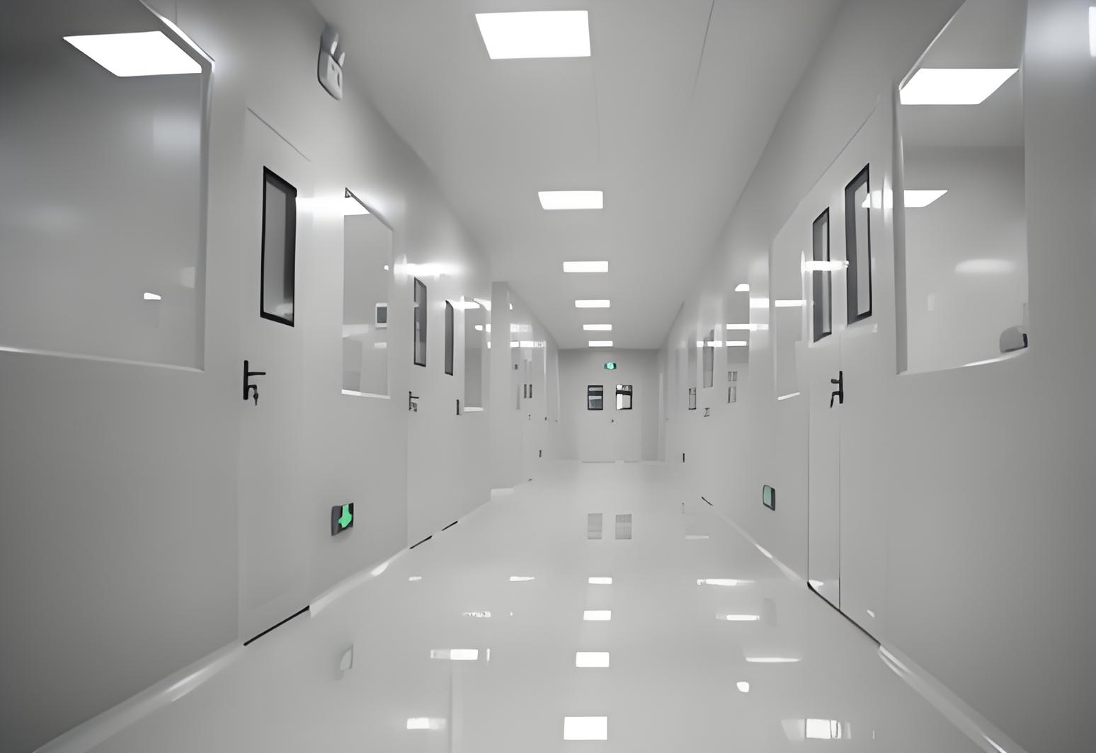
Beyond filter efficiency, the positioning of filters determines the effectiveness of the entire system. Terminal HEPA filters mounted in ceiling diffusers deliver filtered air directly to the critical work zone, minimizing the opportunity for recontamination downstream. In unidirectional airflow configurations—commonly used in ISO 5 (Class 100) environments—the entire ceiling plane is populated with HEPA filters, creating a sweeping curtain of ultraclean air that displaces contaminants toward exhaust grilles at floor level. This arrangement ensures that the cleanest air is always presented to the product or process, a concept that directly informs the design philosophy of Cleanroom Engineering projects.
Filter performance is not static. Pressure drop increases as filters load with captured particles, and physical damage—such as pinholes or seal breaches—can compromise integrity. Routine in-situ testing using aerosol photometry or particle counting verifies that each filter operates within its specified efficiency range. This testing extends to filter housings and gaskets, ensuring that bypass leakage does not undermine the filtration system. The frequency of these tests depends on the cleanroom classification and the criticality of the process, but quarterly or semi-annual schedules are common in pharmaceutical and microelectronics facilities.
Airflow pattern selection ranks among the most consequential decisions in cleanroom design. Two primary airflow regimes exist: unidirectional (laminar) and non-unidirectional (turbulent or mixed). Unidirectional airflow, characterized by parallel air streams moving at uniform velocity (typically 0.45 m/s ± 20%), provides the highest level of contamination control. This configuration sweeps particles away from the work zone in a predictable, one-way path, preventing the recirculation and accumulation of contaminants. Non-unidirectional airflow, in contrast, relies on dilution and mixing to reduce particle concentrations, making it suitable for ISO 7 or ISO 8 environments where product sensitivity is lower.
Pressure differential management operates in tandem with airflow patterns. Maintaining a positive pressure cascade—where air flows from cleaner zones to less clean areas—prevents the ingress of contaminants from adjacent spaces. In a typical pharmaceutical facility, the aseptic filling room (ISO 5) operates at the highest positive pressure relative to surrounding gowning rooms (ISO 7) and general corridors (ISO 8). This pressure hierarchy is enforced through precise HVAC balancing, with air supply volumes exceeding exhaust volumes by a calculated margin. Pressure monitoring devices at room boundaries provide continuous feedback to the building management system, alerting operators to deviations that could signal filter loading, door openings, or HVAC system faults.
The air change rate (ACH)—the number of room volume air exchanges per hour—directly influences cleanroom cleanliness. ISO 5 environments typically require 300–600 ACH, while ISO 7 spaces operate at 30–60 ACH. These high air change rates ensure rapid recovery after contamination events, such as personnel entry or equipment maintenance. Recovery time, defined as the duration required to return to target cleanliness after a disturbance, is a key performance metric for cleanroom validation. Design engineers calculate recovery times based on room volume, air supply rate, and particle generation rates, using these parameters to size HVAC equipment and specify filter banks.
Building on this understanding, the integration of airflow and pressure systems demands careful coordination between mechanical engineers, process engineers, and facility managers. TAI JIE ER brings extensive experience to this coordination, offering engineering solutions that harmonize airflow dynamics with production workflows, ensuring that contamination control does not impede operational efficiency.
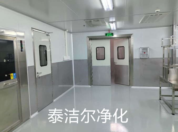
Cleanroom surfaces—walls, ceilings, floors, and workstations—must withstand rigorous cleaning protocols while resisting particle shedding, chemical degradation, and microbial colonization. Material selection begins with an assessment of the production process: pharmaceutical operations often require stainless steel (316L grade) for its corrosion resistance and smooth finish, while semiconductor facilities may favor anodized aluminum or epoxy-coated surfaces to minimize electrostatic discharge and outgassing. The surface finish, measured in terms of roughness average (Ra), directly affects cleanability; Ra values below 0.8 µm are standard for aseptic processing areas.
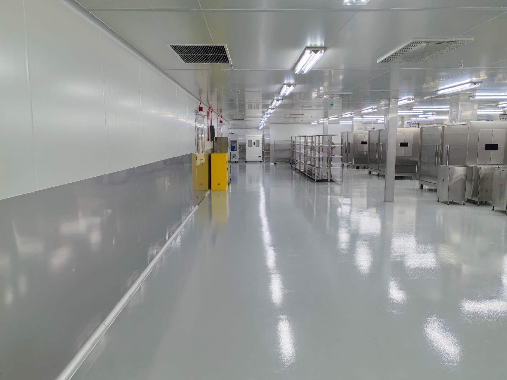
Flooring systems present particular challenges. Epoxy resin or polyurethane seamless floors offer monolithic, joint-free surfaces that eliminate crevices where contaminants could accumulate. These materials are formulated to resist the chemical action of disinfectants—such as hydrogen peroxide, peracetic acid, and quaternary ammonium compounds—while maintaining slip resistance for personnel safety. Coving at wall-floor junctions eliminates right angles, simplifying cleaning and preventing particle entrapment. Similarly, ceiling systems incorporate gasketed grids and flush-mounted fixtures to minimize ledges and recesses where dust could settle.
Outgassing—the release of volatile organic compounds from construction materials—poses a subtle but significant contamination source. In semiconductor cleanrooms, even trace levels of amines or siloxanes can interfere with photolithography processes, causing defects in wafer patterns. Material suppliers provide outgassing test data per standards such as SEMI F21 or ASTM E595, enabling engineers to select low-outgassing adhesives, sealants, and insulation materials. Compatibility with cleaning agents is equally important; materials that degrade or discolor upon exposure to disinfectants compromise both cleanliness and aesthetics, requiring premature replacement.
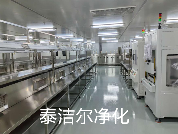
This principle extends to process equipment and furniture. Stainless steel workbenches, polypropylene storage cabinets, and pass-through chambers must be designed with smooth, crevice-free surfaces and rounded corners. Equipment feet and casters should be non-shedding and compatible with cleanroom flooring. TAI JIE ER collaborates with clients to specify materials that balance durability, cleanability, and process compatibility, reducing the risk of material-related contamination events over the facility's lifecycle.
The HVAC system serves as the lungs of any cleanroom, regulating temperature, humidity, and pressure while delivering filtered air to the controlled space. Temperature stability is paramount: in pharmaceutical aseptic processing, even ±1 °C fluctuations can affect product viscosity, filling accuracy, and microbial growth rates. Semiconductor lithography demands even tighter control, with temperature tolerances of ±0.1 °C to maintain mask alignment precision. Humidity, similarly, must be controlled to prevent condensation (which promotes microbial growth) or electrostatic discharge (which damages sensitive electronics). Typical cleanroom humidity ranges from 40% to 60% RH, with variations held to ±5%.
HVAC system design begins with a psychrometric analysis of the facility's location, accounting for external ambient conditions. Air handling units incorporate cooling coils, heating coils, humidifiers, and dehumidifiers in a sequenced arrangement that conditions supply air to the precise setpoint. Energy recovery wheels or heat pipes improve system efficiency by transferring heat between exhaust and supply air streams—an important consideration given the high energy consumption of cleanroom HVAC systems, which can account for 40–60% of a facility's total energy use.
Cleanroom operations cannot tolerate HVAC system downtime. Redundancy is therefore built into critical components: N+1 or 2N configurations for air handling units, chilled water systems, and backup power generators ensure that a single equipment failure does not compromise the controlled environment. Changeover mechanisms allow seamless transitions between primary and standby units, with automatic start-up sequences that maintain pressure and airflow during switching. Alarm systems notify facility engineers of any deviation from setpoints, enabling rapid intervention before product integrity is affected.
Air distribution ductwork must be constructed from non-shedding materials, with smooth internal surfaces to minimize particle accumulation. Duct joints and connections are sealed with gaskets or welded seams to prevent leakage, and access panels are provided for cleaning and inspection. Diffuser design—whether ceiling-mounted or wall-mounted—must achieve uniform air distribution without creating dead zones or jet streams that could stir up settled particles. Computational fluid dynamics (CFD) modeling is increasingly used to visualize airflow patterns and optimize diffuser placement before construction begins.
Personnel represent the largest source of contamination in cleanroom environments. Human skin sheds millions of particles per minute, and activities such as talking, coughing, or rapid movement generate additional aerosolized contaminants. Gowning protocols—including coveralls, hoods, face masks, gloves, and boot covers—serve as the primary barrier between personnel and the cleanroom environment. Gowning materials are selected for their filtration efficiency, low particle shedding, and resistance to disinfectants. Garment changes occur at defined frequencies, with gowning rooms providing a controlled transition zone from non-classified to cleanroom areas.
Beyond gowning, personnel behavior is governed by standard operating procedures (SOPs) that specify movement patterns, workstation ergonomics, and material handling techniques. For example, personnel are trained to move slowly and deliberately, to avoid reaching directly over open product containers, and to minimize the number of times they exit and re-enter the cleanroom. These behavioral protocols are reinforced through periodic training and competency assessments, with violations documented and corrected through quality management systems.
Raw materials, components, and equipment must enter the cleanroom through controlled transfer procedures. Pass-through chambers—airlocks with interlocked doors—allow materials to be surface-cleaned and staged before introduction. For larger equipment, cleanroom-compatible carts and trolleys are used, with wheels that do not shed particles. Transfer procedures include cleaning steps, such as wiping with isopropyl alcohol or applying disinfectant sprays, followed by a dwell time to ensure microbial reduction. Documentation accompanies each transfer, recording the date, time, and personnel involved, creating an audit trail for quality assurance.
Integration between process protocols and cleanroom design is essential. Equipment layouts should facilitate efficient workflows while minimizing cross-traffic between high-risk and low-risk operations. For instance, in a pharmaceutical filling line, the filling machine, stopper hopper, and vial infeed are arranged to maintain unidirectional product flow, with segregated zones for material staging and finished product removal. This integration requires close collaboration between process engineers, cleanroom designers, and operations managers—a collaboration that TAI JIE ER facilitates through comprehensive design-build services that address both facility infrastructure and operational workflows.
A cleanroom is only as reliable as its monitoring program. Continuous monitoring systems track airborne particles, microbial counts, temperature, relative humidity, and pressure differentials in real time. Particle counters, strategically placed at critical process zones, sample air at defined intervals, transmitting data to a central monitoring system that alerts operators to excursions above alert and action limits. Microbial monitoring—typically performed using settle plates, active air samplers, and surface contact plates—provides a complementary assessment of biological contamination, with samples incubated and enumerated over defined periods.
Validation establishes that the cleanroom, as built and operated, meets its specified performance criteria. Initial validation (or commissioning) involves a comprehensive testing regime that includes airflow visualization (smoke studies), filter integrity testing, particle count mapping, and recovery time measurements. Performance qualification (PQ) extends this testing under simulated production conditions, verifying that cleanliness levels remain within limits during normal operations. Revalidation occurs at scheduled intervals—typically every 6 to 12 months—or after any significant modification to the facility or process.
Monitoring data is only valuable if it is accurate, traceable, and systematically analyzed. Modern cleanroom monitoring systems integrate with electronic data capture platforms that store readings in secure databases, preventing unauthorized alterations. Trend analysis identifies gradual degradation in performance—for example, rising particle counts that may indicate filter loading or HVAC system wear—enabling predictive maintenance before failures occur. Statistical process control (SPC) charts are employed to distinguish normal variation from actionable deviations, supporting data-driven decision-making in quality management.
Regulatory bodies such as the FDA, EMA, and WHO expect robust monitoring programs as part of GMP compliance. Documentation of monitoring results, deviations, and corrective actions forms a critical component of the quality system, subject to inspection during regulatory audits. Consequently, cleanroom engineering must extend beyond physical infrastructure to encompass the data systems, reporting procedures, and quality governance that sustain long-term contamination control.
The ISO 14644 series provides the international standard for cleanroom classification and testing. ISO 14644-1 specifies the classification of air cleanliness by particle concentration, with designations ranging from ISO 1 (the cleanest) to ISO 9 (normal room air). Each classification defines maximum allowable particle counts for specific size thresholds: for example, ISO 5 permits 3,520 particles ≥0.5 µm per cubic meter, while ISO 7 allows 352,000 particles ≥0.5 µm per cubic meter. Classification testing involves particle counting at multiple locations within the cleanroom, with statistical analysis to determine compliance.
ISO 14644-2 addresses monitoring and testing for continued compliance, specifying the frequency and methods for periodic testing. ISO 14644-3 covers test methods, including particle count testing, airflow velocity and volume measurements, and filter leak testing. Additional standards—such as ISO 14644-4 (design and construction) and ISO 14644-5 (operation)—provide complementary guidance for the complete lifecycle of cleanroom engineering projects. For pharmaceutical manufacturers, GMP Annex 1 (Manufacture of Sterile Medicinal Products) imposes additional requirements, including mandatory unidirectional airflow for aseptic processing and enhanced monitoring of viable particles.
Recertification ensures that cleanroom performance does not degrade over time. The recertification frequency depends on cleanroom classification and operational intensity: ISO 5 areas typically undergo recertification every 6 months, while ISO 7 and ISO 8 areas may be recertified annually. Recertification replicates the initial validation tests, comparing results against baseline performance and regulatory limits. Any deviation triggers an investigation to identify root causes and implement corrective measures, with documentation maintained as part of the facility's quality records.
Changes to cleanroom configuration—such as installing new equipment, relocating workstations, or modifying HVAC systems—necessitate immediate recertification. This principle ensures that modifications do not inadvertently introduce contamination pathways or disrupt airflow patterns. Engineering change control processes, integrated with quality management systems, govern these modifications, requiring approval from facility engineering, quality assurance, and operations stakeholders before implementation.
Q1: What is the difference between ISO 14644 and GMP cleanroom
classifications?
A1: ISO 14644 provides a generic classification
system based on airborne particle concentration, applicable across industries.
GMP Annex 1, specific to pharmaceutical manufacturing, adds requirements for
microbial monitoring, unidirectional airflow during aseptic processing, and
operational controls. While ISO 14644 defines the physical cleanliness of the
environment, GMP Annex 1 addresses the broader quality system and process
controls necessary for sterile product manufacture. Many pharmaceutical
facilities comply with both, using ISO 14644 for classification and GMP Annex 1
for operational and monitoring protocols.
Q2: How does unidirectional airflow differ from non-unidirectional
airflow in cleanroom design?
A2: Unidirectional airflow (often
called laminar flow) features parallel air streams moving at uniform velocity in
a single direction, typically downward from ceiling HEPA filters to floor
exhausts. This configuration provides the highest level of contamination control
by sweeping particles away from the critical zone. Non-unidirectional airflow
(turbulent or mixed flow) relies on air dilution and mixing to reduce particle
concentrations, with air supplied through multiple diffusers and exhausted at
room level. Unidirectional flow is mandatory for ISO 5 and cleaner environments;
non-unidirectional flow is acceptable for ISO 7 and ISO 8 spaces where product
sensitivity is lower.
Q3: What are the primary sources of contamination in a cleanroom
environment?
A3: Personnel account for 70–80% of contamination
events, primarily through skin particles, hair, and microbial shedding.
Equipment and machinery contribute through moving parts that generate
particulates and wear debris. Raw materials and packaging introduce external
contaminants if not properly cleaned and transferred. Airborne contamination
from the external environment—if filtration and pressure control fail—also poses
a risk. Structural surfaces (walls, floors, ceilings) may shed particles if
materials degrade or cleaning protocols are inadequate. Effective cleanroom
engineering addresses each of these sources through integrated design and
operational controls.
Q4: How often should HEPA filters be tested and replaced in a
cleanroom?
A4: HEPA filter integrity testing—using aerosol challenge
and photometer detection—is typically performed at initial installation, then at
scheduled intervals of 6 to 12 months depending on cleanroom classification and
regulatory requirements. Replacement frequency depends on pressure drop
increase, which indicates filter loading. When the pressure drop reaches 1.5 to
2 times the initial resistance, the filter should be replaced. In
high-particulate environments, filters may last 2 to 5 years; in well-controlled
facilities with efficient pre-filtration, lifetimes of 5 to 8 years are
achievable. Regular monitoring of pressure differentials provides the data for
replacement scheduling.
Q5: What role does material selection play in cleanroom
engineering?
A5: Material selection directly influences
cleanability, particle shedding, chemical resistance, and outgassing. Surfaces
must withstand repeated cleaning with disinfectants and detergents without
degrading or releasing particles. Materials such as 316L stainless steel,
epoxy-coated panels, and seamless polyurethane floors offer smooth, crevice-free
surfaces that resist microbial colonization. Low-outgassing materials prevent
the release of volatile organics that could contaminate sensitive processes like
semiconductor lithography. Material compatibility with the production
process—including temperature, humidity, and chemical exposure—is also evaluated
to ensure long-term performance and regulatory compliance.
Q6: How do pressure differentials prevent contamination spread
between cleanroom zones?
A6: Positive pressure cascades ensure that
air flows from cleaner zones to less clean areas, preventing contaminant
ingress. In a typical pharmaceutical facility, the aseptic core (ISO 5)
maintains the highest positive pressure relative to surrounding ISO 7 gowning
areas and ISO 8 corridors. This pressure gradient is established through HVAC
balancing, with supply air volumes exceeding exhaust and leakage rates by a
calculated margin. Pressure monitoring devices at room boundaries provide
continuous feedback; deviations trigger alarms, prompting corrective actions
such as adjusting dampers or investigating door seal integrity. This dynamic
pressure management is a cornerstone of contamination control in multi-zone
cleanroom facilities.
Q7: What is the significance of air change rate in cleanroom
design?
A7: The air change rate (ACH) determines the speed at which
room air is replaced with filtered air, directly influencing particle removal
and recovery time. Higher ACH values—ranging from 300–600 in ISO 5 environments
to 30–60 in ISO 7 spaces—ensure rapid dilution and removal of contaminants
generated during operations. The ACH is calculated based on room volume, air
supply flow rate, and particle generation rates from personnel and processes.
Engineers select ACH values that balance cleanliness requirements with energy
consumption and HVAC system capacity, recognizing that excessive ACH increases
operational costs without proportional improvement in particle control.
For professional consultation on cleanroom engineering projects—from initial concept and classification to detailed HVAC design, material specification, and validation support—reach out to the engineering team at Cleanroom Engineering for tailored solutions that meet your production integrity requirements. Inquiries regarding design, compliance, or system upgrades are welcome at any stage of your facility lifecycle.


