High-purity manufacturing operations, such as semiconductor fabrication, photovoltaic cell manufacturing, optical device assembly, and biopharmaceutical processing, depend on clean utility infrastructure. Maintaining microscopic contamination controls requires a deep structural alignment between pressurized pneumatic distribution loops and continuous ultrapure water (UPW) recirculation networks. Precision execution in Compressed gas process pure water engineering forms the backbone of these advanced manufacturing environments, ensuring product yield stability and operational repeatability.
The co-location and systematic interplay of high-purity compressed air, dry nitrogen, process inert gases, and UPW create complex fluid dynamic interactions. A failure in moisture extraction upstream in a compressed gas loop can compromise pneumatic valve actuation, resulting in micro-pitting along fluid contact surfaces in pure water distribution networks. Designing these dual-utility facilities requires comprehensive knowledge of metallurgy, polymer science, fluid dynamics, and contamination monitoring.
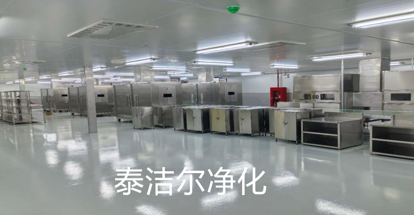
Clean process environments demand strict adherence to purity classifications. Compressed gas supplies—whether CDA (Clean Dry Air), high-purity nitrogen (N2), or argon—act as primary process media, pneumatic control actuators, and blanketing agents. Simultaneously, process pure water loops deliver high-resistivity solvent mediums used in wafer cleaning, active ingredient synthesis, and chemical dilution. The engineering of these two separate utilities intersects at critical process tools and distribution manifolds.
System pressure imbalances between pneumatic actuators and liquid process lines present distinct operational challenges. When gas lines drive pneumatic diaphragm valves controlling pure water flows, micro-leaks in valve diaphragms can cause gas phase intrusion into the liquid stream, inducing cavitation or bubble entrainment. Conversely, liquid back-siphoning into high-purity gas lines degrades desiccant filtration media, resulting in rapid dew point spikes and sub-micron particulate generation.
Atmospheric air compressed to standard operational pressures (typically 0.7 to 1.0 MPa) undergoes a major reduction in relative humidity capacity, leading to rapid water vapor condensation. Moisture in compressed gas loops acts as a breeding ground for bacterial colonies and accelerates localized corrosion in standard metallic piping. Modern protocols in Compressed gas process pure water engineering mandate pressure dew point (PDP) thresholds between -40°C and -70°C.
Achieving these low dew points requires heatless or blower-purge desiccant dryers paired with active molecular sieve beds. Dew point sensors must be installed at header distribution junctions and point-of-use (POU) connections to verify gas dryness prior to entering cleanroom boundaries. Dry gas streams protect hydrophobic PTFE membrane filters used in pure water storage tank venting, preventing membrane wet-out and continuous microbial contamination risks.
Sub-micron particulate contamination degrades semiconductor micro-architecture and disrupts biopharmaceutical sterility. Particles suspended in compressed gas or pure water streams stem from pump impeller wear, valve seat friction, pipe wall erosion, and atmospheric intrusion. Clean utility designs must maintain laminar flow profiles to prevent stagnant boundary layers where particles collect.
Fluid purity depends heavily on the internal surface characteristics of distribution piping networks. High-purity gas distribution and ultrapure water circulation demand distinct material selection parameters based on chemical inertness, extractable profiles, and physical durability.
Clean utility contractors like TAI JIE ER design piping networks that isolate fluid dynamic vibrations and eliminate mechanical failure points along long-distance distribution runs within ISO Class 5 through ISO Class 8 cleanrooms.
Polyvinylidene Fluoride (PVDF) and Polypropylene (PP) represent primary polymer materials used in high-purity process water loops. Unpigmented PVDF is preferred for ultra-high-purity (UHP) loops due to its low level of organic extractables, high thermal stability, and smooth inner surface finish (Ra < 0.25 µm).
Joining PVDF systems requires Bead and Crevice Free (BCF) fusion welding technologies. BCF welding heats pipe ends uniformly and fuses them without creating internal bead protrusion. Internal weld beads introduce fluid turbulence and create micro-eddies where bacteria can colonize. Eliminating internal crevices ensures uniform shear stress along the wall surface, maintaining sanitary fluid transport across the entire loop.
High-purity compressed gas distribution relies primarily on 316L Stainless Steel tubing, modified with low-manganese and low-sulfur chemistries. Internal surfaces undergo electropolishing (EP) to achieve mirror-like finishes with roughness parameters (Ra) consistently below 0.13 µm (5 micro-inches).
Electropolishing removes surface irregularities, reduces total surface area, and enriches the chromium-to-iron oxide ratio on the metal surface. This passive chromium-rich layer prevents chemical reactivity with trace process gases and prevents iron oxidation. Systems constructed by TAI JIE ER incorporate fully automated orbital welding routines under high-purity argon shielding (99.9999% purity) to prevent heat tint, oxidation, and internal weld bead roughing.
Integrating compressed gas and pure water loops within cleanroom ceiling trusses, sub-fab spaces, and service chases demands careful mechanical arrangement. Routing pure water supply lines directly above compressed gas headers or high-voltage control panels creates major operational hazards if pipe flanges or mechanical joints fail.
When implementing Compressed gas process pure water engineering across semiconductor cleanrooms, piping runs are arranged in stacked, segregated utility tracks. Wet utilities run on lower elevations with secondary containment piping, while dry gas utilities occupy higher elevations. This structural separation protects cleanroom floor integrity and prevents moisture ingress into gas distribution panels.
High-speed manufacturing tools require precise volumetric dosing of process pure water, controlled by fast-acting pneumatic diaphragm valves. Compressed air supplying these valve actuators must undergo continuous oil-mist removal via multi-stage coalescing filters down to residual oil concentrations below 0.003 mg/m³.
If micro-droplets of hydrocarbon oil enter pneumatic valve actuators, internal seals degrade over time. Degraded seals cause variable valve response times, resulting in pressure surges (water hammer) throughout the process pure water loop. Water hammer generates mechanical shockwaves that can fracture brittle quartz bath components, dislodge biofilm flakes, or damage delicate reverse osmosis (RO) membrane housing seals upstream.
Point-of-use (POU) connections serve as the final transition point between clean utilities and direct process tool chambers. These points represent high-vulnerability areas where ambient air or trace contaminants can enter the clean utility stream during tool maintenance or line hookups.
Maintaining high utility standards requires constant automated inline analytical monitoring. Real-time telemetry allows facility engineers to detect subtle purity shifts long before process limits are exceeded or product yields suffer.
Execution of robust Compressed gas process pure water engineering projects requires continuous monitoring arrays linked to facility management and control systems (FMCS). These systems log operational parameters, generate automated alarms, and trigger auto-divert mechanisms when quality indicators drift.
Quality parameters for process pure water require ultra-sensitive measurement devices positioned strategically across reverse osmosis, electrodeionization (EDI), and polishing loops.
Gas analytical loops operate continuously to ensure compliance with ISO 8573-1 Class 0 quality standards for CDA and UHP process gases.
Q1: What are the primary mechanisms used to prevent biofilm formation in continuous process pure water distribution loops?
A1: Biofilm prevention relies on maintaining dynamic fluid turbulence with linear velocities between 1.5 and 2.1 m/s throughout the distribution network, eliminating internal dead-legs (maintaining an L/D ratio below 1.5), using smooth PVDF materials with Ra values below 0.25 µm, and utilizing continuous ultraviolet (UV) germicidal irradiation at 254 nm wavelengths combined with periodic thermal or chemical sanitization cycles.
Q2: Why is pressure dew point control critical in clean compressed air systems feeding process equipment?
A2: Excess water vapor in compressed air condenses when line pressures or temperatures drop. Liquid water causes corrosion in distribution piping, causes binding in precision pneumatic actuators, degrades internal seals, and provides the moisture required for biological growth. A consistent pressure dew point of -40°C to -70°C ensures water vapor remains in a gaseous phase, preserving process tool operational integrity.
Q3: How does BCF fusion welding differ from standard socket fusion when joining PVDF piping for UPW loops?
A3: Bead and Crevice Free (BCF) fusion welding utilizes an external heating element and internal inflatable bladder during the heating and cooling cycle. This process forms a perfectly smooth, continuous joint flush with the pipe's inner wall. Standard socket fusion creates internal weld beads and annular gaps that trap particulates, disrupt laminar flow, and serve as colonization sites for biological contaminants.
Q4: What material standards are recommended for UHP compressed nitrogen headers in semiconductor cleanrooms?
A4: UHP compressed nitrogen headers require cold-drawn, electropolished 316L stainless steel tubing with a maximum internal surface roughness (Ra) of 0.13 µm (5 micro-inches). Tubing must undergo strict chemical passivation, ultrasonic solvent cleaning, and orbital argon-purged arc welding to prevent particle generation and outgassing.
Q5: How do oil micro-droplets in compressed air impact downstream pure water processes?
A5: Trace compressor oil vapors pass through standard particulate filters and accumulate on valve seats, diaphragm surfaces, and membrane actuators. Oil causes elastomeric seal swell and physical breakdown, leading to mechanical valve delays. Furthermore, organic oil vapors can migrate into fluid interfaces, increasing Total Organic Carbon (TOC) levels in high-purity water supplies and damaging downstream reverse osmosis membranes.
Designing, constructing, and commissioning complex utility infrastructure demands rigorous mechanical execution, detailed validation protocols (IQ/OQ/PQ), and complete compliance with industry standards. Partnering with experienced providers such as TAI JIE ER guarantees full compliance with ISO cleanroom specifications and international manufacturing standards.
For specialized facility development and compliant Compressed gas process pure water engineering solutions tailored to your operational specifications, submit an engineering Inquiry to our technical design team today.