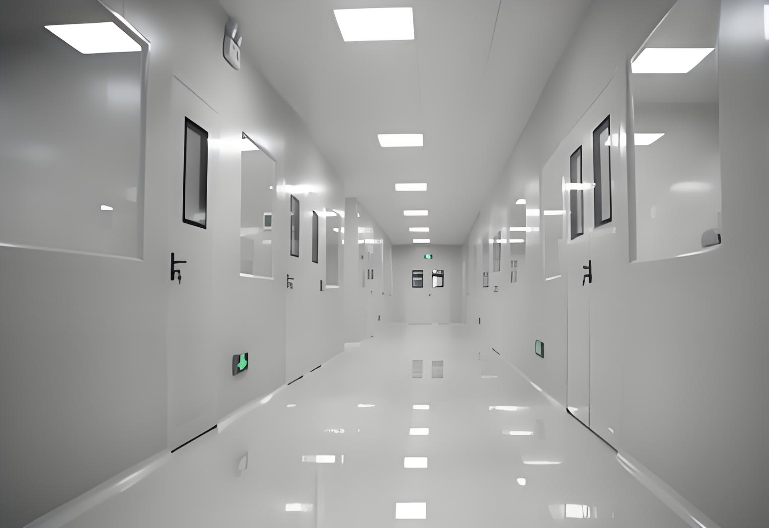
Controlled environments are the backbone of modern pharmaceutical production, medical device assembly, and semiconductor fabrication. At the center of these environments lies Cleanroom design—a disciplined engineering process that integrates airflow management, particle control, material science, and operational protocols. A well-executed cleanroom design does more than meet regulatory checklists; it directly influences yield rates, product consistency, and contamination risk over the entire facility lifecycle.
This article dissects the seven decisive factors that separate functional cleanrooms from high-performance ones. Drawing from decades of field experience and ISO standards, the discussion moves beyond general principles into concrete engineering decisions—each with measurable consequences for air quality, energy consumption, and production uptime.

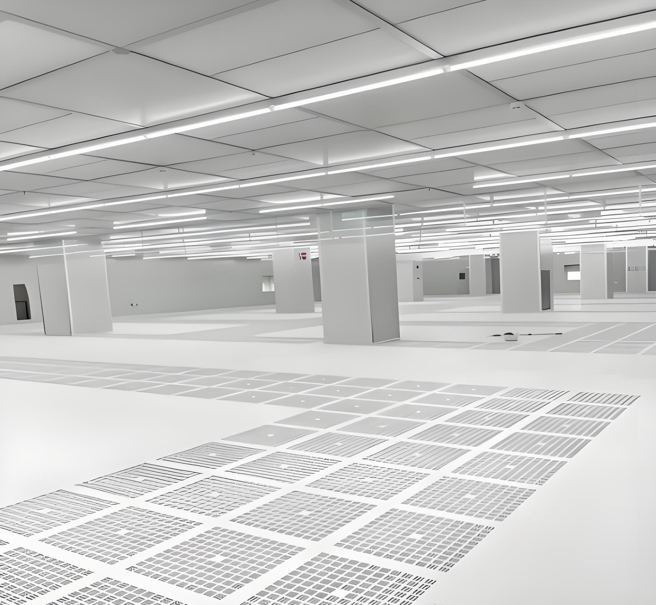
Airflow patterns determine the cleanroom's ability to sweep airborne particles away from critical zones. Cleanroom design must specify between unidirectional (laminar) and non-unidirectional (turbulent) flow based on the required ISO class. For ISO 5 or stricter environments, unidirectional airflow with HEPA or ULPA filters at the ceiling is mandatory. The velocity gradient, typically 0.3–0.5 m/s for vertical flow, must remain uniform across the filter face to avoid eddies that trap particulates.
Filter coverage ratio: For ISO 7 and ISO 8, 15–25% ceiling coverage suffices; for ISO 5, 80–100% coverage is required.
Return air strategy: Low-wall returns paired with ceiling supply creates a piston-like sweep. Floor-level returns are avoided in pharmaceutical settings to prevent re-entrainment.
Air change rates: ISO 5 demands 400–600 air changes per hour (ACH), while ISO 8 operates at 20–50 ACH. These values directly affect HVAC sizing and fan energy.
Airflow modeling using computational fluid dynamics (CFD) has become standard in modern cleanroom design. CFD simulations reveal dead zones, thermal plumes from equipment, and personnel-induced turbulence—information that cannot be obtained from theoretical calculations alone. Manufacturers who skip CFD often face costly retrofits when particle counts exceed limits during live production.
Maintaining positive pressure differentials between adjacent spaces is a non-negotiable aspect of cleanroom design. The pressure hierarchy ensures that contaminants from lower-grade areas do not migrate into higher-grade zones. A typical cascade ranges from 15 Pa to 30 Pa between classifications, with the most critical suite holding the highest pressure.
Pressure monitoring: Digital manometers with alarms at each airlock provide real-time visibility. Pressure decay tests during commissioning validate the envelope's leak-tightness.
Door interlocks: Interlocked pass-through chambers and personnel airlocks prevent simultaneous opening of two doors, which would collapse the pressure differential.
Buffer zones: Grade D to Grade C to Grade B cascades are typical in sterile manufacturing. Each step requires dedicated HVAC zones with independent pressure control.
Pressure integrity is not merely a design consideration—it is a continuous operational discipline. Over time, filter loading, door seal wear, and HVAC drift can erode differentials. Therefore, a robust cleanroom design includes automatic pressure reset algorithms that compensate for filter degradation, keeping the cascade stable without manual intervention.
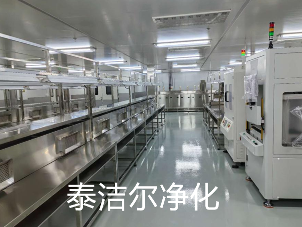
Materials used inside a cleanroom directly influence particle generation, chemical resistance, and cleanability. Cleanroom design specifications must address walls, ceilings, floors, workstations, and even utility piping with equal rigor.
Wall panels: Modular sandwich panels with non-shedding surfaces—powder-coated steel, stainless steel, or reinforced fiberglass—are preferred. Joints must be sealed with epoxy or silicone that withstands frequent disinfection.
Flooring: Seamless epoxy or polyurethane flooring provides a monolithic surface that resists chemical attack and supports heavy equipment. Cove bases eliminate right-angle corners where dust accumulates.
Work surfaces: Stainless steel 304 or 316L with a No. 4 finish offers corrosion resistance and ease of cleaning. Perforated or slotted surfaces are avoided because they trap residues.
Beyond static material properties, the manufacturing process for these materials matters. For instance, panels that arrive with protective film residue can outgas volatile organic compounds (VOCs) once inside the cleanroom. A thorough cleanroom design includes a material qualification protocol that tests for outgassing, abrasion resistance, and compatibility with sterilization agents like hydrogen peroxide vapor.
The HVAC system is the largest consumer of energy in a cleanroom facility, often accounting for 50–70% of total electricity usage. Consequently, cleanroom design must balance strict air quality requirements with energy efficiency—without compromising the former.
Chilled water and hot water loops: Precise temperature control (±0.5°C) is achieved through dedicated coils with modulating valves. Oversizing chillers leads to short cycling and humidity swings.
Humidity management: Relative humidity is maintained at 40–60% to prevent electrostatic discharge and microbial growth. Desiccant wheels or chilled-water dehumidifiers are specified based on local climate.
Variable air volume (VAV) vs. constant air volume (CAV): VAV systems reduce fan speed during unoccupied periods, provided that pressure cascades remain intact. CAV is simpler but less efficient for facilities with intermittent operations.
An overlooked aspect of HVAC integration is the placement of sensors. Temperature and humidity sensors must be located in representative zones—not near supply diffusers or heat-generating equipment. A well-designed cleanroom design incorporates sensor redundancy and averaging algorithms to prevent false readings that trigger unnecessary HVAC adjustments.
Cleanroom design extends beyond physical infrastructure; it encompasses the movement of people, materials, and products. Poorly planned workflows introduce cross-contamination risks and reduce throughput.
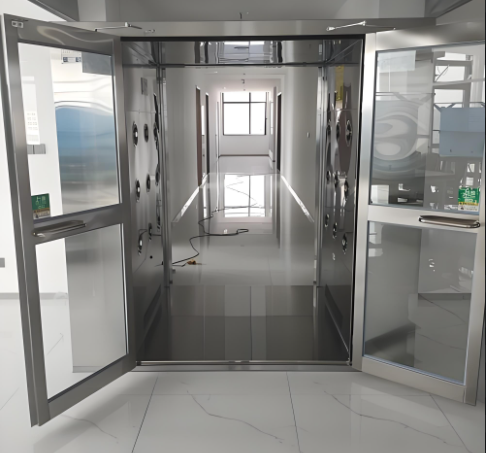
Personnel gowning sequences: Changing rooms are designed with step-over benches and separate storage for street clothes and cleanroom garments. Air showers at the final gowning stage remove loose particles from the outer surface.
Material transfer: Pass-through chambers with HEPA-filtered air showers or chemical decontamination ports allow raw materials and finished products to enter and exit without breaching pressure barriers.
Segregated corridors: Material corridors and personnel corridors are physically separated in high-potency facilities to prevent cross-contamination between active ingredients and packaging lines.
Simulation-based workflow optimization is increasingly employed during the cleanroom design phase. Discrete-event modeling assesses the impact of batch size, gowning time, and equipment cleaning cycles on overall equipment effectiveness (OEE). This quantitative approach often reveals bottlenecks that are invisible on paper diagrams.
Utilities—including compressed air, purified water, vacuum, and process gases—must be integrated into the cleanroom design without compromising the controlled environment. Each utility penetration through the envelope is a potential leak path that requires careful sealing.
Utility panels: Pre-fabricated utility walls with quick-connect fittings reduce on-site fabrication work and minimize dust generation during installation.
Maintenance corridors: Service plenums above the ceiling and below the raised floor provide access to filters, dampers, and piping without entering the production zone.
Filter change-out protocols: Bag-in/bag-out filter housings allow safe replacement of contaminated HEPA filters without exposing workers to hazardous particles.
Maintenance access is often sacrificed in initial cleanroom design to maximize production floor space. This trade-off backfires when filter changes require production shutdowns or when utility failures lead to extended downtime. Including dedicated service corridors and labeling all utility endpoints significantly reduces mean time to repair (MTTR) in operational facilities.
Regulatory bodies—including the FDA, EMA, and WHO—mandate that cleanroom design comply with ISO 14644-1:2015 classification and GMP Annex 1 (for sterile products). However, compliance is not a one-time achievement; it requires ongoing verification and documentation.
Design qualification (DQ): Ensures that the cleanroom design meets the user requirement specification (URS) before construction begins.
Installation qualification (IQ) and operational qualification (OQ): Validate that installed systems perform according to design parameters, including airflow velocity, pressure differentials, and particle counts.
Performance qualification (PQ): Conducted under simulated production conditions to confirm that the cleanroom consistently maintains its classification.
A comprehensive cleanroom design integrates the documentation framework from the outset. Rather than treating qualification as a post-construction activity, forward-thinking designers embed test ports, sampling points, and sensor networks that facilitate routine re-qualification. This approach reduces the administrative burden and ensures that any deviation is detected early.
Across these seven factors, one underlying theme emerges: cleanroom design is an interdisciplinary endeavor. It demands collaboration among HVAC engineers, process architects, quality assurance specialists, and production managers. Cleanroom design that neglects any single factor often results in compromised performance—either through elevated particle counts, excessive energy bills, or operational inflexibility.
For organizations planning new facilities or upgrading existing ones, the decision to invest in a well-structured cleanroom design pays dividends throughout the asset's lifetime. TAI JIE ER has been at the forefront of delivering customized cleanroom solutions that address these exact challenges—from initial conceptualization through to commissioning and validation. The company's engineering team applies first-principles analysis to every project, ensuring that the final cleanroom design aligns with both regulatory standards and production targets. TAI JIE ER also provides ongoing support for requalification and system optimization, helping facilities adapt to evolving product portfolios and stricter environmental guidelines.
The discussion above illustrates that cleanroom design is not a static blueprint but a dynamic framework that responds to operational data, technological advances, and regulatory shifts. Facilities that treat cleanroom design as a living process—rather than a one-off engineering deliverable—consistently outperform peers in product purity, yield, and regulatory inspection outcomes.
Q1: What is the most overlooked aspect of cleanroom design in pharmaceutical facilities?
A1: Personnel training integration is frequently neglected. Even the most sophisticated cleanroom design cannot compensate for improper gowning, poor aseptic technique, or incorrect material transfer. Designers should incorporate training spaces, visual aids, and simulated workflows during the commissioning phase to ensure operators understand not only how to move but why each movement matters.
Q2: How does cleanroom design differ for semiconductor manufacturing versus sterile drug production?
A2: Semiconductor cleanrooms prioritize particle control at sub-micron levels (down to 0.1 µm) and electrostatic discharge (ESD) prevention. Pharmaceutical cleanrooms emphasize microbial control, chemical cross-contamination avoidance, and smooth surfaces for disinfectant application. While both follow ISO standards, the HVAC dehumidification load and material compatibility requirements diverge significantly.
Q3: Can an existing building be retrofitted with a high-grade cleanroom design?
A3: Yes, but with constraints. Ceiling height, structural column spacing, and existing HVAC capacity are limiting factors. Retrofit projects often require raised floors for underfloor air supply or external air-handling units. A detailed feasibility study, including structural load calculations and plenum routing, is necessary before committing to a retrofit cleanroom design.
Q4: What validation tests are mandatory after completing a cleanroom design?
A4: At minimum, the following tests are required: airflow velocity and uniformity, pressure differential mapping, particle count (at rest and in operation), filter integrity (DOP/PAO challenge), temperature and humidity uniformity, and recovery time (the duration required to return to cleanliness after a contamination event). These tests form the basis of ISO 14644-3 certification.
Q5: How often should a cleanroom design be re-evaluated after commissioning?
A5: Annual re-qualification is standard for most regulated industries. However, any change in production process, equipment layout, or HVAC system modification triggers a partial re-validation. Many facilities now adopt continuous monitoring systems that provide real-time data, enabling proactive adjustments and reducing the scope of periodic re-qualification.
For inquiries regarding your specific cleanroom design requirements, including ISO class selection, HVAC load calculations, and modular construction options, please contact our engineering team. TAI JIE ER offers turnkey services from concept design to operational handover. Cleanroom design expertise is available for facilities ranging from R&D pilot lines to full-scale commercial production suites.


