

In semiconductor fabrication, biotechnology, and advanced pharmaceutical manufacturing, contamination directly determines product yield and patient safety. Cleanroom design is not merely about installing HEPA filters — it involves a systematic engineering discipline that integrates airflow physics, material compatibility, process workflows, and real-time monitoring. A properly executed cleanroom design reduces particle ingress, prevents cross-contamination, and ensures compliance with ISO 14644-1 and EU GMP Annex 1. This article provides a detailed technical framework for facility managers, project engineers, and validation specialists seeking robust, scalable contamination control solutions.
1. Foundational Elements of Modern Cleanroom Design
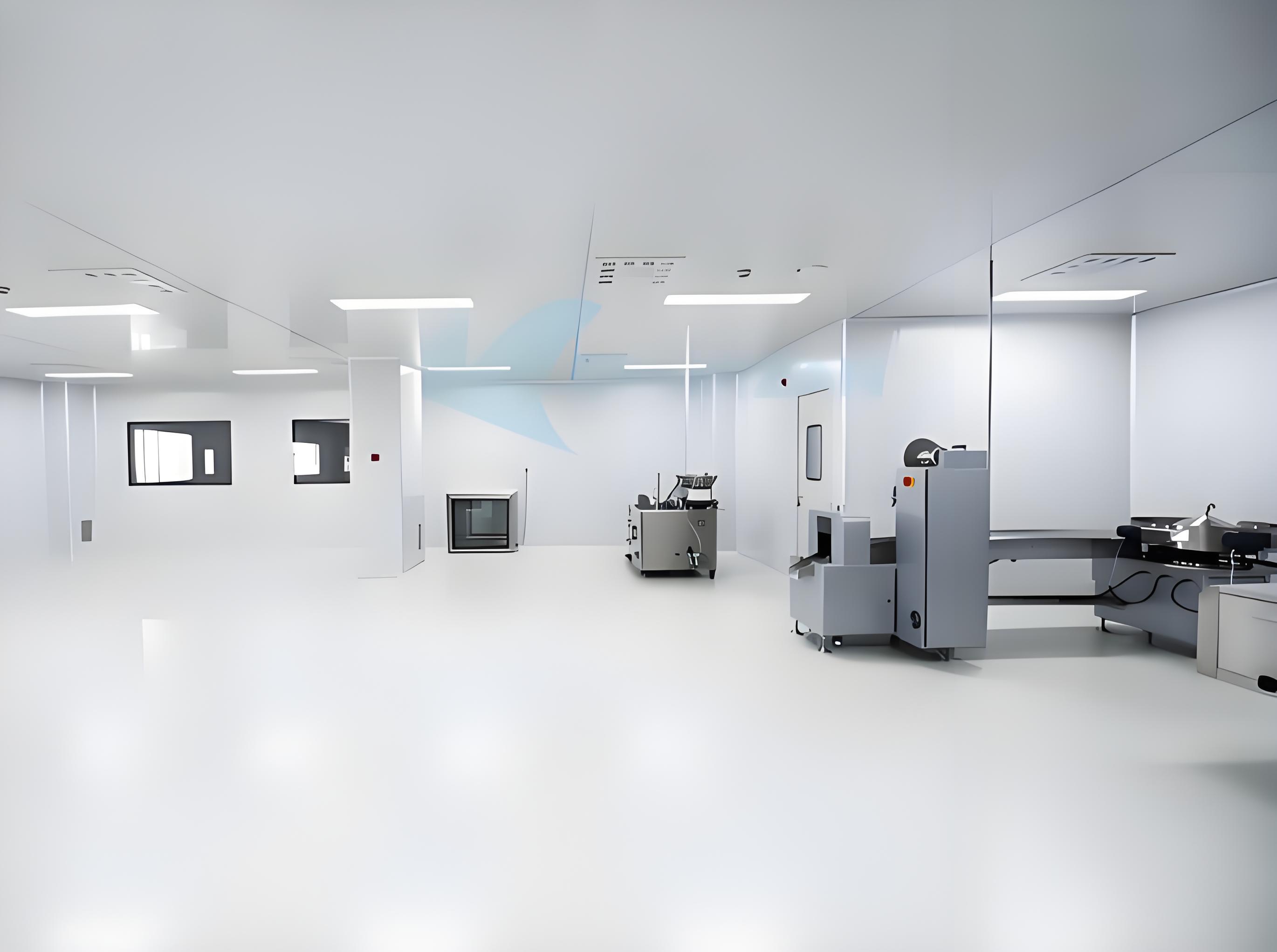
Every contamination-controlled environment begins with three non-negotiable pillars: airflow configuration, architectural finishes, and operational zoning. These elements must be defined before specifying HVAC equipment or selecting filter grades.
1.1 Airflow Patterns and Velocity Gradients
Unidirectional (laminar) flow is mandatory for ISO 5 or Class 100 environments, requiring velocities between 0.36–0.54 m/s at the working plane. For ISO 6–8 spaces, non-unidirectional (turbulent) flow with high air change rates (20–90 ACH) remains acceptable. The transition zone between unidirectional and turbulent areas must be designed with velocity decay modelling to avoid eddy currents that trap particles. Computational fluid dynamics (CFD) simulations are now standard practice in cleanroom design to visualize stagnation zones and optimize diffuser layouts.
1.2 Construction Materials and Surface Integrity
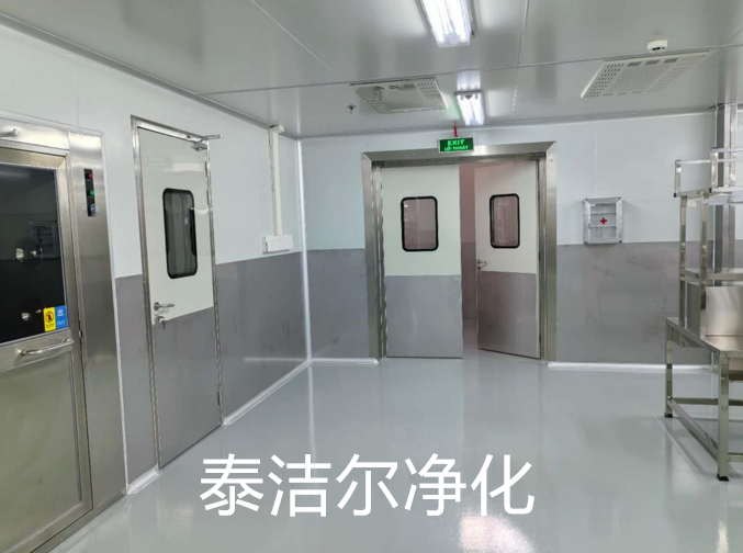
Wall and ceiling panels should feature seamless, non-porous finishes — powder-coated steel, modular aluminum-framed panels, or fiberglass-reinforced plastic (FRP). Floors require epoxy or polyurethane resin systems with cove bases to eliminate crevices. Material selection must withstand daily cleaning with hydrogen peroxide vapor or quaternary ammonium compounds without degradation. TAI JIE ER integrates prefabricated modular panels that meet ISO Class 4–8 requirements, reducing on-site fabrication debris by nearly 40% compared to conventional stick-built construction.
2. Technical Parameters That Govern Cleanroom Performance
Beyond basic classification, five engineering metrics dictate operational reliability: air change rate (ACH), differential pressure (ΔP), recovery time, particle count profiles, and filter installation leakage. Each parameter must be verified during dynamic conditions (equipment running, personnel present).
Air Change Rates (ACH): ISO 8: 20–25 ACH; ISO 7: 30–60 ACH; ISO 6: 60–90 ACH; ISO 5: 240–480 ACH (unidirectional). Higher ACH does not automatically mean better cleanliness — excessive turbulence can resuspend settled particles.
Pressure Cascade: Maintain +10–15 Pa between clean corridor and adjacent unclean area; +15–20 Pa between cleanroom and external warehouse. Differential pressure alarms should trigger at a 5 Pa deviation.
Recovery Time: The period required to return to target cleanliness after a contamination event (e.g., filter change or maintenance). ISO 7 spaces typically require 15–20 minutes; ISO 5 requires less than 5 minutes.
HEPA/ULPA Efficiency: HEPA H14 (≥99.995% MPPS) for ISO 7 and above; ULPA U15 (≥99.9995%) for ISO 5 critical zones. Scan testing per IEST-RP-CC034.2 is mandatory.
Non-viable vs. Viable Monitoring: Real-time particle counters (0.5 µm and 5.0 µm) paired with active microbial air samplers — settle plates alone are insufficient for modern regulatory audits.
3. ISO Classifications and Their Direct Impact on Design Decisions
Selecting the correct ISO class drives every downstream engineering choice. The table below illustrates how classification dictates air volume, filter coverage, and gowning protocols.
ISO 5 (Class 100): Full unidirectional flow, terminal HEPA filters covering ≥80% of ceiling area, full-body sterile suits. Used for aseptic filling, semiconductor photolithography.
ISO 6 (Class 1,000): Mixed flow; 50–60% ceiling filter coverage; minimum 90 ACH; two-piece gowning with hoods. Suited for medical device assembly, sterile packaging.
ISO 7 (Class 10,000): Non-unidirectional; 20–30% filter coverage; 30–60 ACH; gowning: coveralls, gloves, masks. Common in pharmaceutical compounding, bioburden control.
ISO 8 (Class 100,000): 15–20% filter coverage; 20–25 ACH; smocks and hairnets. Used for ancillary zones, component preparation, and food contact surfaces.
A frequent error in cleanroom design is over-specifying ISO 5 for all zones, which increases fan energy by 300-400% and requires frequent filter replacement. Instead, apply a risk-based approach: grade only critical exposure areas at ISO 5, while supporting spaces operate at ISO 7/8. TAI JIE ER applies this gradient strategy, achieving 35% lower HVAC energy consumption compared to uniform high-class designs.
4. Industry-Specific Pain Points and Engineered Solutions in Cleanroom Design
4.1 Contamination from Personnel (the Largest Source)
Humans shed 100,000–10 million particles per minute (0.3–10 µm). Standard gowning reduces this by factor 100–500, but improper gowning sequences nullify efforts. Solutions:
Design gowning rooms with an “air shower” at the transition from gray to clean zone (minimum 25 m/s nozzle velocity).
Implement partition benches (dirty-to-clean) with floor marking indicating step-off points.
Install particle counters at gowning exit to validate gowning effectiveness each shift.
4.2 Cross-Contamination Between Different Product Lines
Multi-product facilities face risks of airborne API or biologic cross-transfer. Engineering controls include:
Physical barriers: solid walls instead of soft curtains when handling potent compounds (OEB 4/5).
Dedicated HVAC zones: separate air handling units for each production suite with 100% exhaust (no recirculation).
Pass-through autoclaves or vaporized hydrogen peroxide chambers for material transfer between zones.
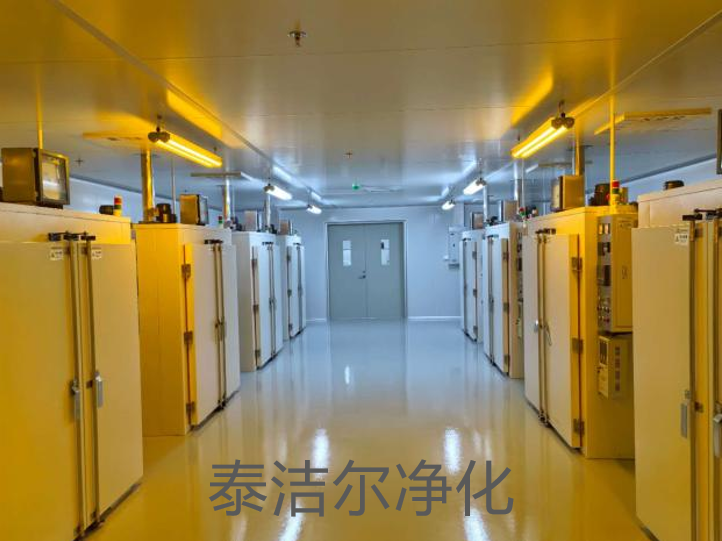
4.3 Airflow Stagnation Behind Equipment
Poorly placed bioreactors, isolators, or filling machines create “dead zones” where particles accumulate. Remediation:
Raise equipment on 150–200 mm legs to allow sweep airflow underneath.
Install perforated raised floor panels in unidirectional flow areas to return air uniformly.
Use smoke studies (ASTM E3264-20) during commissioning to visualize and correct wake regions.
5. Advanced Strategies for Contamination Control Beyond Standard Cleanroom Design
Modern facilities integrate active monitoring with predictive maintenance. Real-time particle and microbial sensors (ISO 14644-14:2016) provide trending data that alerts operators before intervention levels are exceeded. Two emerging approaches are changing the field:
Risk-based monitoring frequency: Instead of fixed sampling points, use computational flow modeling to locate highest-risk positions (e.g., near doors, transfer hatches).
Automated decontamination cycles: Hydrogen peroxide bio-decontamination systems integrated into the HVAC control logic allow rapid room turnaround between campaigns without manual wiping.
For aseptic processes, isolator-linked cleanroom design reduces background classification to ISO 7 instead of ISO 5, lowering operational complexity. TAI JIE ER provides fully integrated control platforms that link particle counters, differential pressure transmitters, and HVAC damper positions into a single BMS interface, enabling immediate alarm-driven responses.
6. Material and Construction Techniques for Long-Lasting Cleanrooms
6.1 Wall-to-Floor Seam Detailing
Traditional cove bases (50 mm radius) still permit dirt accumulation at junction points. Newer “zero-joint” monolithic flooring where the resin extends 150 mm up the wall eliminates the crevice entirely. Welded PVC flooring with hot-air welded seams provides equivalent performance in modular structures.
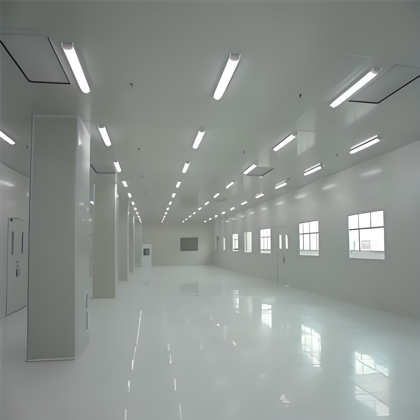
6.2 Lighting and Utility Penetrations
Recessed LED fixtures with flush polycarbonate lenses prevent particle shedding. All utility passthroughs (gas, water, vacuum lines) must be sealed with non-porous silicone grommets that withstand repeated cleaning with 70% IPA. Avoid exposed conduit — use service poles or interstitial ceilings.
6.3 Modular vs. Conventional Construction
Modular wall systems (aluminum framework with snap-in panels) reduce construction lead time by 30-50% and allow future reconfiguration. They also produce far less on-site cutting debris than drywall construction. However, modular panels require careful attention to sealing at the ceiling grid intersection — gasketed compression seals are mandatory to bypass leakage.
7. Integration of Monitoring and Control Systems into Cleanroom Design
Today’s facilities cannot rely on manual logbooks. A valid cleanroom design incorporates:
Continuous differential pressure monitoring with graphical trend display at the access door.
Remote Particle Counters (28.3 L/min for non-viable, 100 L/min for viable air samplers) that upload data to SCADA.
Temperature and RH stability: ±1°C and ±5% RH for most GMP processes; tighter (±0.5°C/±2% RH) for stability testing rooms.
Audit trail and alarm management compliant with 21 CFR Part 11 or EU Annex 11.
Alarm parameters should be set at 80% of action limits (e.g., alarm at 12 Pa when action limit is 15 Pa) to allow corrective action before deviation occurs. The monitoring system must be validated for data integrity (ALCOA+ principles) during the facility qualification phase.
8. Frequently Asked Questions (Cleanroom Design Engineering)
Q1: What is the difference between ISO 7 and ISO 8 cleanroom design in terms of HVAC specifications?
A1: ISO 7 requires 30–60 air changes per hour (ACH) with 20–30% ceiling HEPA coverage, typically using FFU (fan filter unit) arrays. ISO 8 operates at 20–25 ACH with 15–20% filter coverage, often served by a central AHU with terminal HEPA boxes. Additionally, ISO 7 spaces demand pressure differentials ≥15 Pa relative to adjacent unclassified areas, while ISO 8 requires ≥10 Pa. The difference in filter fan energy consumption is approximately 2.5–3× higher for ISO 7.
Q2: How can we minimize particle resuspension in a non-unidirectional cleanroom design?
A2: Resuspension occurs when supply air jets impinge on work surfaces or floors. Solutions: (a) use low-velocity swirl diffusers (terminal velocity <0.2 m/s at 1.5 m height); (b) increase return grilles at low wall level (≤300 mm above floor); (c) implement raised access flooring with 30% open area for underfloor return; (d) avoid locating workbenches directly under supply diffusers. CFD modeling is highly recommended to verify recirculation patterns before construction.
Q3: What validation documents are mandatory after completing a new cleanroom design project?
A3: At minimum, the following are required for regulated industries: (i) Design Qualification (DQ) — verifying specifications against user requirements; (ii) Installation Qualification (IQ) — filter scan tests, air volume balance, and material certificates; (iii) Operational Qualification (OQ) — non-viable particle counts (static and dynamic), air change rates, pressure cascade, recovery test; (iv) Performance Qualification (PQ) — microbial monitoring (viable particles) over three consecutive shifts plus worst-case simulation. Additionally, provide an as-built HEPA filter location drawing with unique IDs for each filter.
Q4: Can we use stainless steel for all surfaces in a cleanroom design to improve cleanability?
A4: While stainless steel (304 or 316L) is excellent for workbenches, equipment panels, and pass-through boxes, it is cost-prohibitive and thermally conductive for entire walls/ceilings. Full stainless construction causes condensation risk in cold climates and requires complex seam welding. A more practical approach: use epoxy-painted aluminum or FRP panels for walls, stainless steel only for wetted zones (sink areas, filling nozzles), and seamless resin floors. Avoid stainless on ceilings — reflective glare interferes with lighting uniformity.
Q5: What are the most common design flaws found during aseptic cleanroom certification?
A5: Based on certification audits, frequent flaws include: (a) insufficient door undercuts (should be 10–20 mm for pressure balancing); (b) missing pressure relief dampers between zones with high differentials; (c) HEPA filter support grids without airtight sealing, causing bypass leakage; (d) no particle monitoring data during simulated interventions; (e) low return air grilles blocked by equipment. Remediating these after construction adds substantial costs, emphasizing that cleanroom design must include operability reviews during the detailed engineering phase.
Project-Specific Inquiry – Cleanroom Design & Engineering
For custom ISO/GMP cleanroom layouts, HVAC performance simulations, and modular construction schedules, forward your detailed inquiry to our engineering team. TAI JIE ER provides end-to-end support from conceptual design through to certified validation. Please include your required ISO class, room dimensions, and process type (e.g., aseptic fill, semiconductor etching, medical device assembly). A technical proposal with GA drawings, filter layout, and pressure cascade diagrams will be returned within five business days.
Send inquiry via the official contact portal: https://www.taijieer.com/ — reference “Cleanroom design consultation” for prioritized engineering review.

