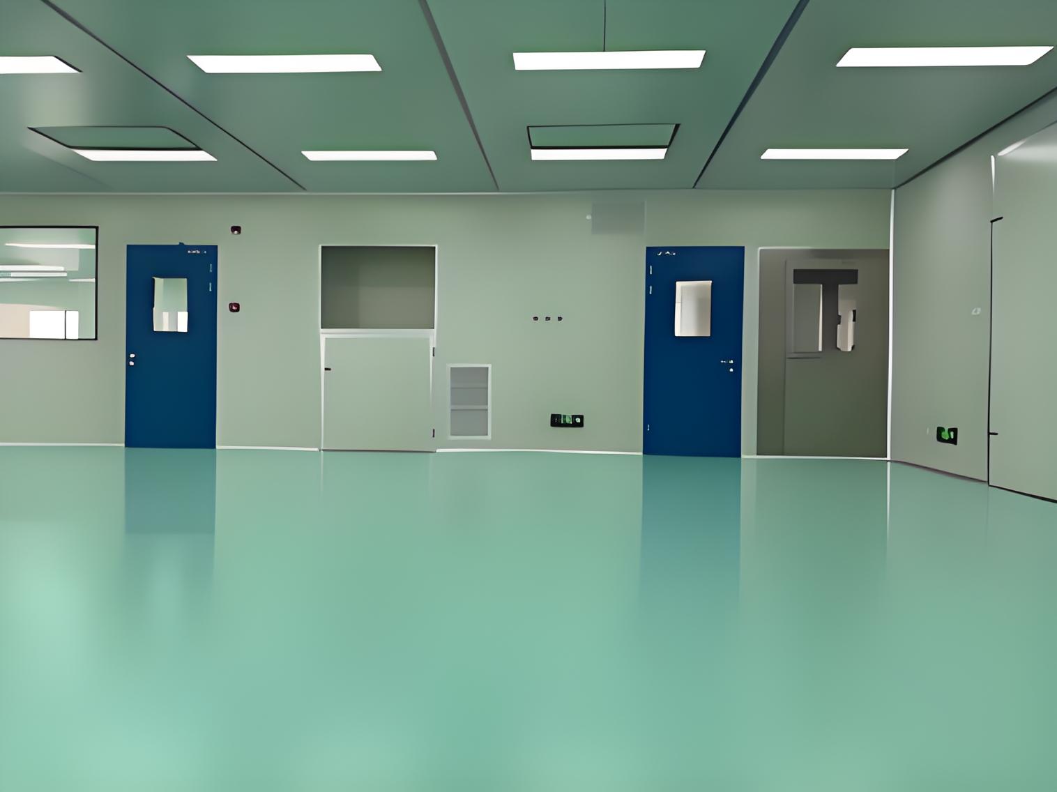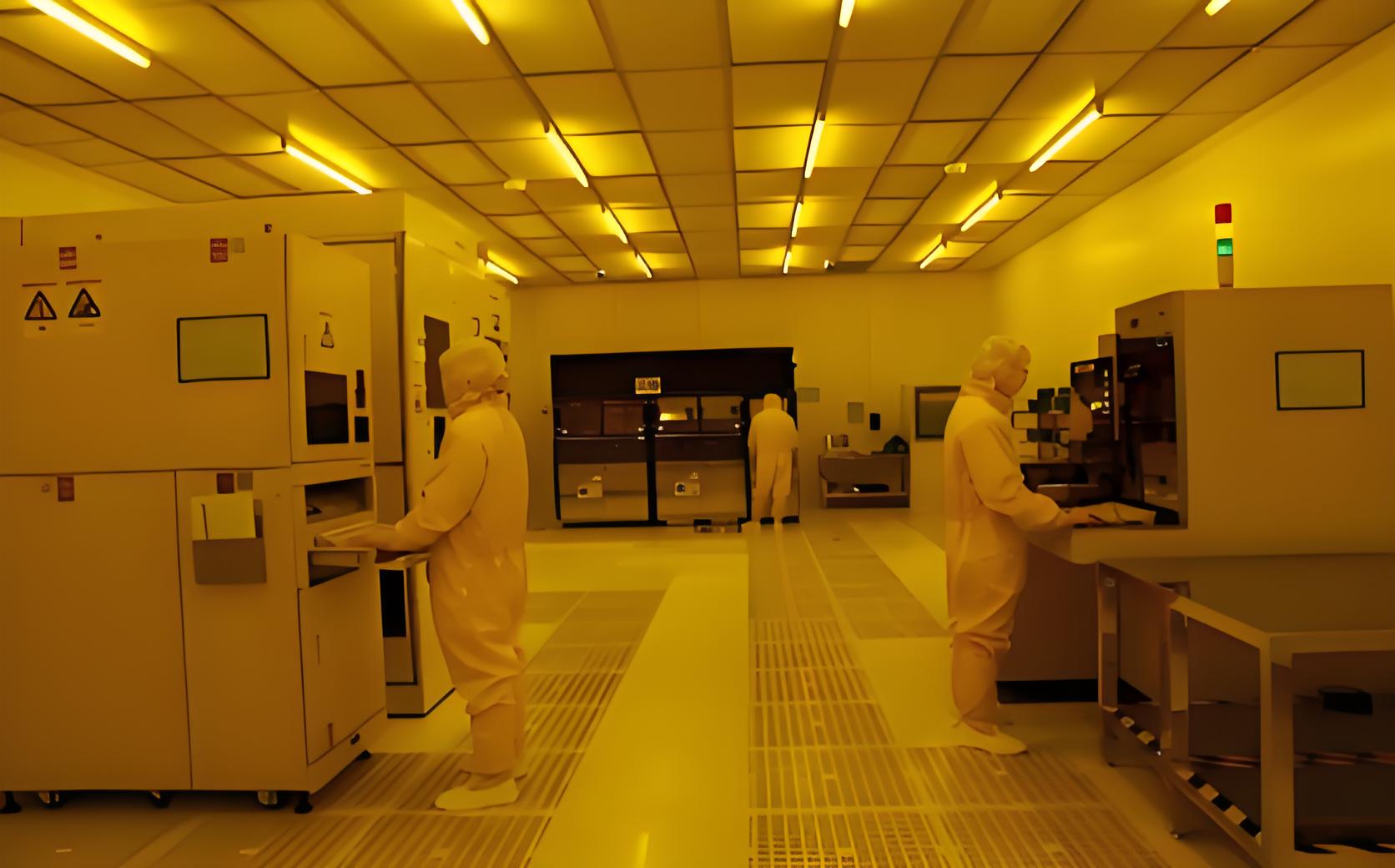
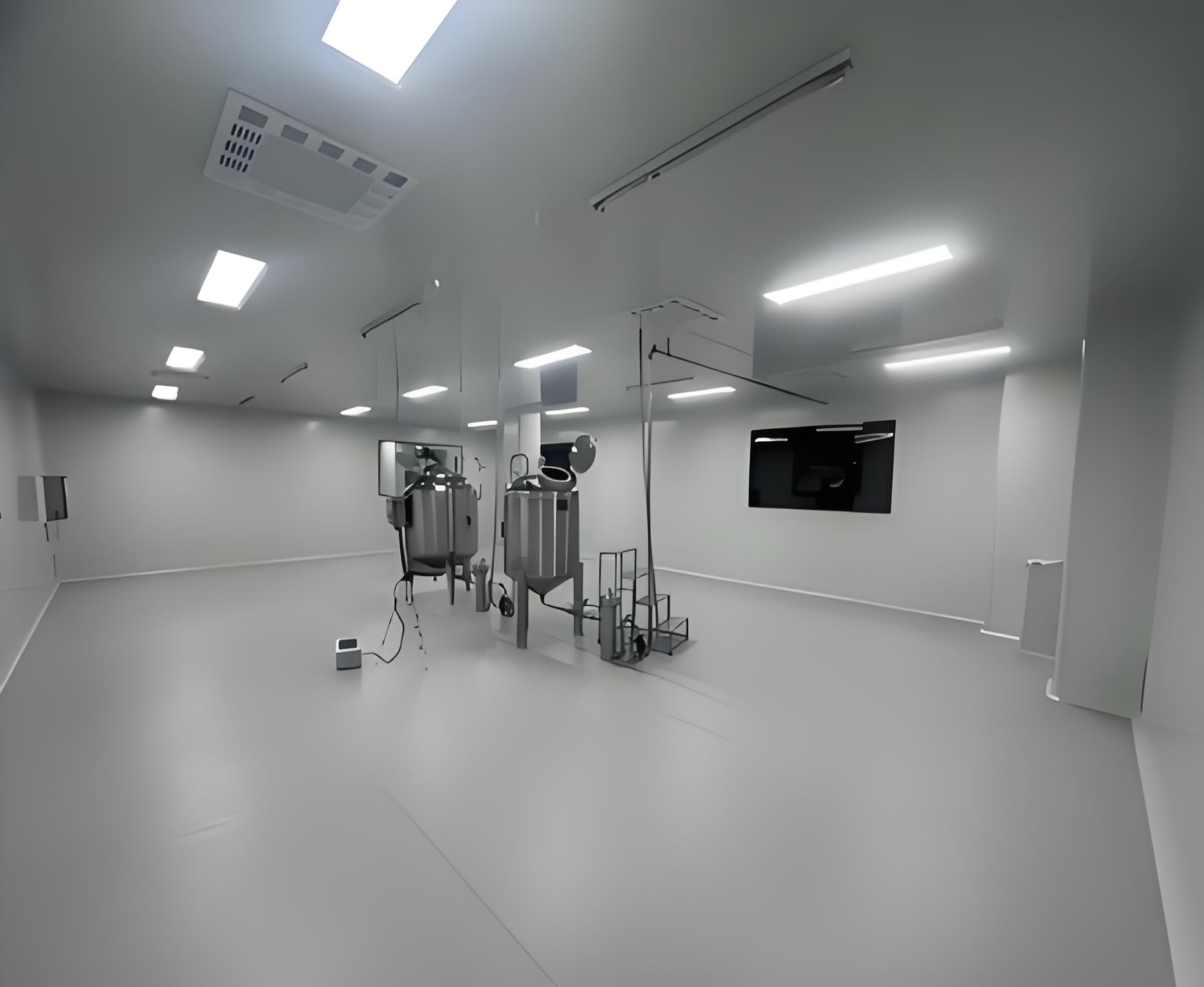
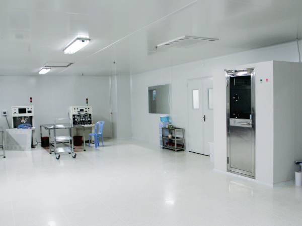
As electronic components shrink toward molecular scales, cleanroom contamination control becomes a primary driver of manufacturing yield and reliability. Standard atmospheric air contains millions of microscopic suspended particles per cubic meter. In the context of semiconductor wafer fabrication, flat panel display assembly, or high-density printed circuit board manufacturing, a single sub-micron dust particle can bridge electrical pathways, causing permanent wafer failure. Implementing a structured system of Electronic purification engineering establishes an environment where particle counts, airflow velocity, pressure differentials, molecular contaminants, and relative humidity are controlled to exact parameters.
Providers of integrated cleanroom systems, such as TAI JIE ER, develop advanced environmental designs to prevent particulate ingress and cross-contamination. Modern microelectronics facilities demand classification standards ranging from ISO Class 1 to ISO Class 5, which require specialized engineering methods to sustain. Achieving these cleanroom environments depends on a deep understanding of fluid dynamics, materials science, and atmospheric chemistry.
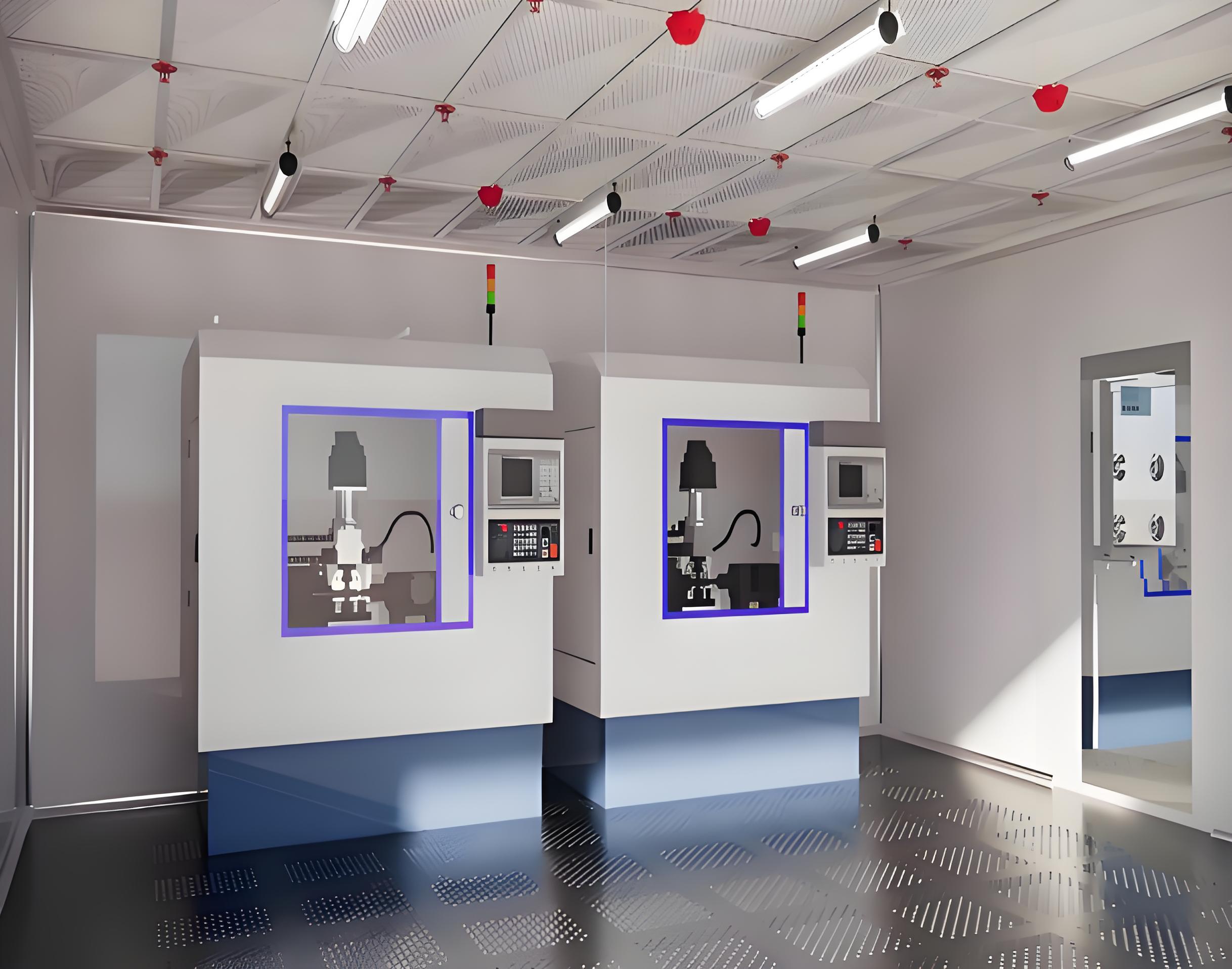
Airflow direction and velocity dictate how particles are swept away from wafer-handling zones. In standard environments, turbulent air moves unpredictably, allowing suspended particles to settle on clean substrates. Cleanroom designs replace this chaotic movement with controlled, predictable air paths.
Laminar flow systems maintain uniform, parallel streams of clean air moving downward or horizontally. This prevents turbulence, which can otherwise re-entrain particles and deposit them onto clean substrates. In highly sensitive areas, such as photolithography bays, vertical laminar flow ensures that any particulate shed by machinery or personnel is immediately driven downward into the raised floor grilles. Non-unidirectional (turbulent) flow is utilized in lower-tier cleanrooms, relying on clean air dilution to reduce overall particle concentration.
High-Efficiency Particulate Air (HEPA) filters capture 99.97% of particles down to 0.3 micrometers. Ultra-Low Penetration Air (ULPA) filters increase this efficiency to 99.999% for particles down to 0.12 micrometers. These filters use interceptive, inertial, and diffusional mechanisms to trap contaminants. Proper sealing of filter frames within the ceiling grid is necessary to prevent bypass leaks, which can ruin cleanroom integrity.
Cleanrooms maintain positive pressure relative to adjacent areas. This pressure gradient, typically between 10 to 15 Pascals, prevents untreated outside air from infiltrating the controlled space when access doors are opened. Fan Filter Units (FFUs) containing integrated blowers and filters are distributed across the ceiling grid to maintain the required Air Change Rates (ACR), which can exceed 500 changes per hour in ISO Class 1 areas.
Particulate filtration alone does not address gaseous contaminants. Gaseous elements, static charges, and micro-vibrations represent significant structural hurdles that must be addressed to protect sub-micron electronics during assembly.
Airborne Molecular Contamination (AMC) refers to chemical vapors, gases, and aerosols that can react with wafer surfaces, leading to chemical staining, oxide degradation, or unintended doping. AMCs are classified into four primary categories:
To control AMC, modern Electronic purification engineering solutions incorporate chemical filters containing activated carbon, chemically impregnated alumina, or ion-exchange resins. These media selectively adsorb or chemisorb gaseous impurities from both the recirculating air and the fresh makeup air stream.
Static electricity poses a significant threat to microchips during the manufacturing phase. Electrostatic charges can accumulate on surfaces and discharge rapidly through sensitive circuits, destroying trace paths. Cleanroom construction must feature electrostatic dissipative (ESD) materials for flooring, wall panels, and work surfaces. These materials allow controlled decay of static charges to the ground. Relative humidity (RH) is kept within a tight band, typically 45% to 55%, to balance electrostatic and chemical demands. If humidity drops below 40%, the probability of electrostatic buildup increases. Conversely, if humidity rises above 55%, wafer surfaces can suffer from oxidation, and photoresists can experience adhesion failures.
Implementing high-precision humidification and dehumidification loops within the HVAC system ensures compliance with these narrow operating windows. For complex system integration, specialized service providers like TAI JIE ER integrate customized humidity-control units capable of holding tolerances within +/- 2% RH.
Photolithography tools rely on precise optical alignment to print circuit patterns at nanoscale levels. Even minor floor vibrations can cause misalignment, leading to exposure errors and reduced wafer yield. To isolate precision equipment from vibration caused by HVAC units, pumps, and foot traffic, cleanrooms utilize structural isolation joints. The floor under lithography tools is built on isolated concrete plinths that are disconnected from the surrounding cleanroom floor structure.
Different manufacturing sectors require tailored approaches to cleanliness, based on the susceptibility of their products to environmental anomalies.
| Application Sector | Primary Contamination Focus | Typical ISO Class Target | Core Filtration Requirement |
|---|---|---|---|
| Semiconductor Wafer Fabs | 0.1μm particles, AMC (Dopants/Acids) | ISO Class 1 to ISO Class 5 | ULPA (U15-U17) + Chemical Filtration |
| Flat Panel Display (FPD) | Large-area dust deposition, Organic outgassing | ISO Class 5 to ISO Class 6 | HEPA/ULPA + Hydrocarbon filters |
| SMT / PCB Assembly | Solder residue, Humidity-induced oxidation | ISO Class 7 to ISO Class 8 | HEPA (H13-H14) + ESD Flooring |
Each sector relies on specific engineering methodologies to balance environmental cleanliness with operational demands. For example, flat panel display manufacturing involves large glass substrates that attract dust due to static forces, requiring extensive ionizer integration alongside laminar airflow. Semiconductor foundries, on the other hand, prioritize AMC removal to prevent the degradation of ultra-thin gate oxides.
Before a cleanroom can begin production, it must undergo a rigorous validation sequence to confirm compliance with ISO 14644 standards. Maintaining compliance in Electronic purification engineering requires continuous monitoring and structured qualification stages.
Testing methodologies include using laser particle counters to verify concentration limits across designated grid zones, measuring velocity profiles at the filter face and work plane level, and conducting aerosol challenge tests (such as PAO/DOP testing) to detect pinhole leaks in HEPA/ULPA filters. Organizations looking to establish these certified environments rely on the execution capabilities of specialized firms. For example, TAI JIE ER designs and builds environments to meet strict ISO class criteria, handling everything from initial air balance verification to final particulate certification.
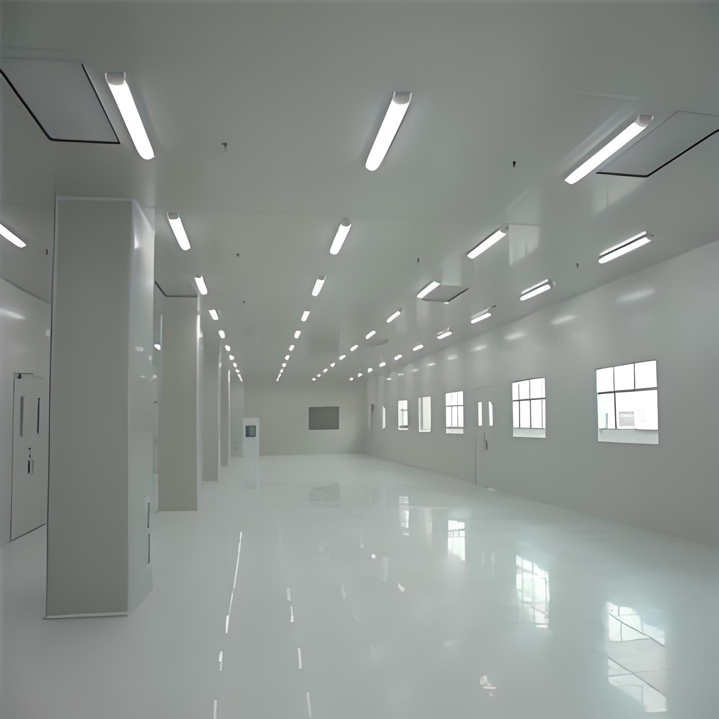
The materials used to build the physical envelope of a cleanroom are just as important as the filtration systems. Wall panels, ceiling grids, and floor coverings must resist physical wear, chemical sanitization agents, and potential outgassing.
Standard building materials can release volatile organic compounds (VOCs) and silicones over time, contributing to chemical contamination. Modern cleanrooms utilize double-skin metal sandwich panels finished with powder coatings or PVC linings that prevent outgassing. Joints and seams are sealed with specialized cleanroom-grade polyurethane sealants that cure without releasing chemical vapors. These smooth, non-porous surfaces prevent particle accumulation and simplify the regular cleaning protocols required to maintain cleanroom classification.
The push toward smaller node sizes in chip manufacturing drives the adoption of Microenvironments or Front-Opening Unified Pods (FOUPs). Instead of maintaining an entire room at ISO Class 1, the surrounding cleanroom is kept at ISO Class 5, while the wafers are sealed inside mini-environments maintained at ISO Class 1 or better with continuous nitrogen purging. This approach refines chemical filtration and precise environmental control, providing a localized micro-climate for wafer transport.
Advanced Electronic purification engineering strategies focus on integrating these automated transport systems with the overall cleanroom architecture to minimize human exposure, which remains the primary source of particulate contamination in clean environments.
Establishing a modern microelectronics cleanroom requires coordinating HVAC engineering, civil construction, automation, and testing. A disjointed design approach can lead to mismatched system components, airflow imbalances, and failed validation runs. Partnering with an engineering provider that manages both design and construction phases helps streamline execution and prevent compatibility issues. Selecting a specialist in Electronic purification engineering ensures that structural systems, air handling units, and filtration loops are designed to work together, supporting consistent manufacturing yields and stable long-term operation.
Partners like TAI JIE ER offer end-to-end design, procurement, construction, and testing services, allowing electronics manufacturers to secure certified cleanrooms that comply with global validation frameworks.
Q1: What is the primary difference between ISO Class 5 and ISO Class 7 cleanrooms in electronics manufacturing?
A1: ISO Class 5 and ISO Class 7 cleanrooms differ primarily in their allowable airborne particle concentrations and the required Air Change Rates (ACR). An ISO Class 5 environment allows a maximum of 3,520 particles of size 0.5 microns or larger per cubic meter of air, typically requiring laminar unidirectional airflow and an ACR of 240 to 480 changes per hour. An ISO Class 7 environment allows up to 352,000 particles of size 0.5 microns per cubic meter and is sustained via non-unidirectional turbulent airflow with an ACR of 60 to 90 changes per hour.
Q2: How does Airborne Molecular Contamination (AMC) affect semiconductor fabrication?
A2: AMC consists of gaseous chemical impurities that pass through standard HEPA/ULPA filters. When these molecules deposit on wafer surfaces, they can cause unintended doping, alter dielectric properties, or lead to chemical corrosion of microscopic circuitry. These issues lead to chip defects and overall yield loss, which is why chemical filtration using activated carbon and molecular media is required.
Q3: Why is relative humidity control so strict in microelectronics cleanrooms?
A3: Relative humidity must be kept within a strict window (typically 45% to 55% RH) to manage two competing issues. Low humidity levels (below 40%) promote electrostatic discharge (ESD) events that can burn out microcircuits. High humidity levels (above 55%) accelerate surface oxidation of metallic components and can cause photoresist layers to lose adhesion during lithography.
Q4: What testing methods are used to verify cleanroom filter integrity?
A4: Filter integrity is verified using aerosol challenge testing, commonly referred to as the PAO (polyalphaolefin) or DOP (dioctyl phthalate) test. An aerosol is introduced upstream of the HEPA/ULPA filter, and a photometer or discrete particle counter is used downstream to scan the filter face and housing seams. Any detected penetration exceeding 0.01% indicates a leak that must be sealed or repaired.
Q5: How do FFU-based systems compare to ducted air handling units in cleanroom designs?
A5: Fan Filter Units (FFUs) operate as localized filtration modules with dedicated motors, offering modular flexibility and easier cleanroom expansion. Ducted air handling units rely on a centralized blower to force air through terminal filters, which simplifies centralized motor maintenance. FFU designs are widely favored in high-cleanliness zones (ISO Class 1-5) due to their ability to easily cover 100% of the ceiling grid without requiring massive centralized fan systems.
Engineering teams planning to build, upgrade, or certify a controlled manufacturing environment are invited to consult with our cleanroom design specialists. Contact our B2B project division to discuss your specific ISO classification goals, structural envelope options, and mechanical systems integration requirements.