
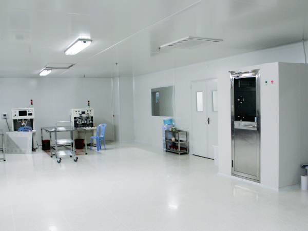
In advanced manufacturing environments, such as semiconductor fabrication facilities and pharmaceutical plants, minor contamination can lead to significant production losses. A single microscopic particle or trace organic compound can ruin an entire production batch, costing millions of dollars.
While engineers often treat compressed gases and ultrapure water (UPW) as independent utilities, their critical intersection point is frequently overlooked. This intersection is the core focus of modern Compressed gas process pure water engineering.
| System Phase | Process Medium | Key Operational Parameter | Risk Vector at Intersection |
|---|---|---|---|
| High-Purity Gas Phase | Nitrogen, CDA, or Argon | Moisture level, hydrocarbons, particles | Direct diffusion into the water phase |
| Pure Water Phase | Ultrapure or Purified Water | Resistivity, TOC, bacterial count | Absorption of gas-phase impurities |
Historically, cleanroom design separated gas distribution from water purification. However, contemporary process demands require a unified approach. When high-purity nitrogen gas blankets a pure water storage tank, any impurity in the gas phase directly impacts the liquid phase.

Defining the Core Integration Challenge
At its foundation, Compressed gas process pure water engineering involves the systematic integration of clean compressed gases with high-purity water generation and distribution systems. These systems are not merely adjacent; they are operationally interdependent.
In a standard high-purity setup, the gas and water systems interface directly at the headspace of the storage vessels. The compressed gas delivery system provides the positive pressure head, while the purified water distribution system draws from the liquid phase below.
In microelectronics and biotechnology, process water must maintain ultra-low levels of dissolved oxygen, total organic carbon (TOC), and particulate matter. Compressed gases, such as nitrogen (N2) or clean dry air (CDA), are used to transport, blanket, or pressurize this water.
If the gas delivery system introduces micro-particles, hydrocarbons, or moisture, the water chemistry degrades rapidly. Achieving balance between these two phases requires specialized knowledge of surface chemistry, fluid dynamics, and cleanroom protocols.
The Interfacial Contamination Blind Spot
A common oversight in cleanroom design is treating gas purification and water treatment as separate systems. Traditional engineering designs often assign these utilities to different engineering teams.
This separation creates a vulnerability at the interface: the point where the gas contacts the pure water. For example, during nitrogen blanketing of a pure water tank, pressure drops can draw ambient air through faulty vent valves.
| Process Stage | Phase Condition | Downstream Impact on Utility Purity |
|---|---|---|
| 1. Mechanical Fault | Vent valve leak or seal wear | Atmospheric air bypasses the barrier and enters the headspace. |
| 2. Gas Phase Exposure | Air mixes with pure nitrogen | Oxygen, carbon dioxide, and organics dilute the gas blanket. |
| 3. Liquid Phase Diffusion | Gas impurities dissolve into water | Water resistivity drops rapidly and TOC measurements spike. |
When ambient air enters, carbon dioxide dissolves into the water, forming carbonic acid. This chemical reaction increases conductivity and lowers pH.
By analyzing the system as a unified process, engineers can prevent contamination rather than addressing water chemistry issues after they occur.
Technical Analysis of the Gas-Water Interface
To successfully execute Compressed gas process pure water engineering, engineers must address three primary technical dimensions.
1. Materials Science and Surface Chemistry
The materials used in piping, valves, and gaskets must be chemically inert and resistant to leaching. For pure water systems, Polyvinylidene Fluoride (PVDF) and electropolished 316L stainless steel are standard choices.
| Material Class | Primary Application | Key Risk Factor |
|---|---|---|
| PVDF (High Temp) | Hot pure water loops, chemical delivery | Thermal expansion mismatches at joints |
| 316L SS (EP) | High-pressure gas lines, water storage | Rouging formation (iron oxide migration) |
| PTFE / TFM | Valve diaphragms, sealing gaskets | Cold flow deformation under high pressure |
For gas lines contacting pure water, the surface roughness (Ra) of stainless steel piping should be less than 0.25 μm via electropolishing. This smooth finish prevents particulate entrapment and microbial adhesion.
2. Pressure Dynamics and Backflow Prevention
Fluctuations in demand can cause rapid pressure changes within water storage tanks. If water pressure drops below gas pressure, gas can enter the water distribution pumps, causing cavitation.
Conversely, if gas pressure drops suddenly, water can backflow into the gas delivery lines, causing microbial growth in dry piping. Automated control loops with high-precision pressure transmitters are essential to maintain a stable pressure differential.
3. Gas Blanketing Optimization
Nitrogen blanketing prevents ambient oxygen from dissolving into pure water. Oxygen supports aerobic bacterial growth and oxidizes sensitive semiconductor components.
| System Element | Input Parameter | Purity Control Mechanism |
|---|---|---|
| Gas Supply | High-Purity Nitrogen (>99.999%) | Restricts atmospheric oxygen contact with water surface |
| Vessel Headspace | Low-pressure nitrogen blanket | Maintains a positive pressure barrier against ambient air |
| Exhaust / Vent | 0.2 μm Hydrophobic Filter | Prevents particulate and microbial ingress during draw-down |
The nitrogen used must be at least 99.999% pure. The system requires a hydrophobic vent filter (typically 0.2 μm PTFE) to allow gas to escape during tank filling while preventing external microbial entry.
The Dual-Phase Purity Matrix (DPPM)
To help engineers evaluate and manage these interfaces, we developed the Dual-Phase Purity Matrix (DPPM). This framework organizes gas-phase contaminants and liquid-phase metrics into a structured risk-assessment tool.
| Gas-Phase Contaminant | Impacted Liquid Parameter | Primary Mitigation Vector |
|---|---|---|
| Particulates (>0.1 μm) | Liquid Particulate Count | Multi-stage gas membrane filtration |
| Hydrocarbons / VOCs | Total Organic Carbon (TOC) | Catalytic oxidation & active carbon filtration |
| Oxygen / Carbon Dioxide | Conductivity / Dissolved Oxygen | High-purity nitrogen blanketing (>99.999%) |
The DPPM identifies three main contamination pathways:
Particulate Migration: Mechanical wear in gas regulators can release particles into the water tank. These particles serve as nucleation sites for mineral scale and bacterial biofilms.
Organic Outgassing: Trace hydrocarbons from poor-quality elastomers in gas valves can dissolve into the pure water, raising TOC levels.
Dissolved Gas Equilibrium: Carbon dioxide in the purge gas can alter water pH, skewing conductivity measurements used for water quality monitoring.
Cleanroom Engineering Solutions
At TAI JIE ER, our engineering approach focuses on minimizing these interface risks. We design integrated cleanroom utilities to ensure that gas and water systems operate dependably together.
| Process Stage | Utility Component | Engineering Function |
|---|---|---|
| 1. Input | Gas Generation & Water Treatment | Pre-purification of core feed streams |
| 2. Conditioning | Coalescing Filtration & UV Sterilization | Elimination of droplets, particles, and viable microbes |
| 3. Delivery | Integrated Distribution Header | Balanced delivery to point-of-use with real-time feedback |
Our designs incorporate double-block-and-bleed valve arrangements on all gas-to-water interfaces. This setup prevents cross-contamination during maintenance cycles.
Additionally, we use orbitally welded piping systems to eliminate mechanical joint failures. This approach minimizes leak points and helps maintain system purity over extended operating periods.
Commissioning Checklist for Gas-Water Interfaces
This checklist helps verify the integrity of your gas-water interface before commissioning.
[ ] Material Verification: Confirm all gas-phase piping in contact with pure water is electropolished 316L SS with certified mill test reports.
[ ] Helium Leak Testing: Perform a helium leak test on all gas line joints, targeting a leak rate of less than 1 × 10⁻⁹ mbar·L/s.
[ ] Hydrophobic Vent Check: Verify the nitrogen blanket tank vent filter is a hydrophobic PTFE membrane rated at 0.2 μm or smaller.
[ ] Passivation Quality: Ensure all stainless steel surfaces have undergone citric or nitric acid passivation, verified by copper sulfate testing.
[ ] Backflow Simulation: Test the pressure control loop under simulated power loss to ensure backflow preventers seal correctly.
[ ] Instruments Calibration: Calibrate all dissolved oxygen meters and gas-phase pressure transmitters against traceable standards.
Addressing Industry Doubts
Can industrial-grade compressed air power pneumatic valves near pure water loops?
Using standard industrial air for control valves near pure water systems is not recommended. If a valve diaphragm fails, industrial-grade air can leak directly into the pure water stream, introducing lubricants and particulate matter.
| Parameter | Standard Utility Air | Clean Dry Air (CDA) |
|---|---|---|
| Hydrocarbon Risk | High (compressor oil carryover) | Ultra-low (monitored and filtered) |
| Particulate Load | Variable (piping scale and dust) | Controlled to ISO Class 1 or 2 standards |
| Diaphragm Failure Impact | Immediate process contamination | Minimal impact on water resistivity |
We recommend using instrument-grade Clean Dry Air (CDA) for all pneumatic devices located inside cleanrooms and near pure water infrastructure.
How does nitrogen blanketing pressure affect pure water tank structural integrity?
Pure water storage tanks are often thin-walled vessels designed for low-pressure storage. Even minor over-pressurization during nitrogen blanketing can cause structural damage or failure.
| Pressure Extreme Scenario | Primary System Cause | Operational Consequence |
|---|---|---|
| Over-Pressurization | High nitrogen flow with restricted exhaust | Tank deformation and structural joint failure |
| Vacuum Implosion | Rapid water draw-down with gas supply failure | Tank collapse due to external atmospheric pressure |
The system requires high-sensitivity breathing valves and rupture disks calibrated to low pressures (typically between 50 and 150 mm water column) to balance gas flow and fluid volume changes.
Is PVDF always superior to 316L stainless steel for high-purity systems?
While PVDF offers excellent chemical resistance and releases fewer metal ions, it is susceptible to mechanical deformation at elevated temperatures and pressures.
For high-pressure gas delivery and high-temperature sanitization loops (above 80°C), electropolished 316L stainless steel remains the preferred option. The selection should depend on your operating temperatures, pressures, and sanitization protocols.
Frequently Asked Questions
Q1: What are the primary standards governing compressed gas process pure water engineering?
A1: These systems are primarily guided by SEMI standards (such as SEMI F19 for piping materials), ISPE Baseline Guides for Water and Steam Systems, and ASTM D5127 for electronic-grade water purity levels.
Q2: How often should the hydrophobic vent filters on pure water tanks be tested?
A2: We recommend performing integrity testing (such as water intrusion or bubble point tests) on hydrophobic vent filters at least once every six months, or immediately following any major system pressure variations.
Q3: What role does TOC play in water systems when exposed to compressed gases?
A3: Compressed gases can carry trace hydrocarbons from compressor lubricants. If these gases contact pure water, the hydrocarbons dissolve, raising the Total Organic Carbon (TOC) level. This increase can promote bacterial growth and interfere with delicate surface reactions.
Q4: Can compressed nitrogen gas introduce microbial contamination to pure water?
A4: Yes. If the nitrogen generation or distribution system is not sterile, bacterial spores can survive in gas piping. Once introduced to a water tank, these spores can colonize the system. Using sterile-grade gas filters at the point of use helps mitigate this risk.
Q5: What is the recommended pressure delta between compressed gas blanketing and water storage?
A5: The nitrogen blanketing gas pressure is typically maintained slightly above atmospheric pressure, between 2 and 5 mbar (approx. 20 to 50 mm water column). This positive pressure prevents ambient air infiltration without over-pressurizing the water storage vessel.