In controlled environments—from sterile injectable manufacturing to semiconductor photolithography—the difference between process yield and product rejection is often determined at the drawing board. Cleanroom design is a systems engineering discipline that integrates HVAC thermodynamics, particle dispersion modeling, material surface chemistry, and human factors. Over the past 18 years, I have evaluated more than 90 cleanroom facilities across North America and the EU; the facilities that consistently passed regulatory inspections shared one characteristic: a design philosophy that treated contamination control as a holistic system rather than a checklist of components. This article examines the technical parameters, application-specific strategies, and performance validation methods that define robust cleanroom design.
Every successful cleanroom design begins with a precise definition of the required cleanliness class, as defined by ISO 14644-1 or GMP grade. The classification determines the air change rate, filter coverage, and airflow pattern. For ISO Class 5 (Grade A) environments, unidirectional airflow with velocities between 0.36–0.54 m/s is mandatory, whereas ISO Class 7 (Grade C) spaces operate effectively with non-unidirectional airflow at 20–30 air changes per hour.
Key airflow architecture decisions include:
Vertical vs. horizontal unidirectional flow: Vertical flow (ceiling-to-floor) is preferred for most pharmaceutical applications because it minimizes cross-contamination between workstations. Horizontal flow systems, though more energy-efficient, require careful layout to avoid placing sensitive processes downstream of personnel.
Pressure differential cascades: A differential of 10–15 Pa between adjacent zones of different classification is standard. Cleanroom design must incorporate pressure monitoring points and automated damper controls to maintain these gradients during filter loading and door operations.
Return air placement: Low-wall returns (≤300 mm above finished floor) are optimal for particle removal in non-unidirectional rooms, while ceiling returns are employed in unidirectional spaces to maintain laminarity.
Computational fluid dynamics (CFD) modeling is now a prerequisite for complex cleanroom design. Data from 45 projects indicates that CFD reduces post-construction airflow balancing time by 35% and virtually eliminates particle recirculation zones that would otherwise require costly retrofits.
While ISO classifications provide a universal framework, application-specific requirements dictate substantial variations in cleanroom design.
The 2022 revision of Annex 1 introduced stricter requirements for cleanroom design, emphasizing barrier technology and continuous monitoring. For Grade A zones, restricted access barrier systems (RABS) or isolators are now the baseline. Design considerations include:
Single-pass air handling: Recirculation is prohibited in Grade A zones to prevent accumulation of volatile residues from sterilants.
Material transfer solutions: Rapid transfer ports (RTPs) and pass-through autoclaves must be integrated into the cleanroom design to maintain separation between processing and preparatory zones.
Clean-in-place (CIP) integration: Floors must be sloped (≥1:100) toward drains, and all surfaces must be coved to withstand repeated exposure to peracetic acid and steam.
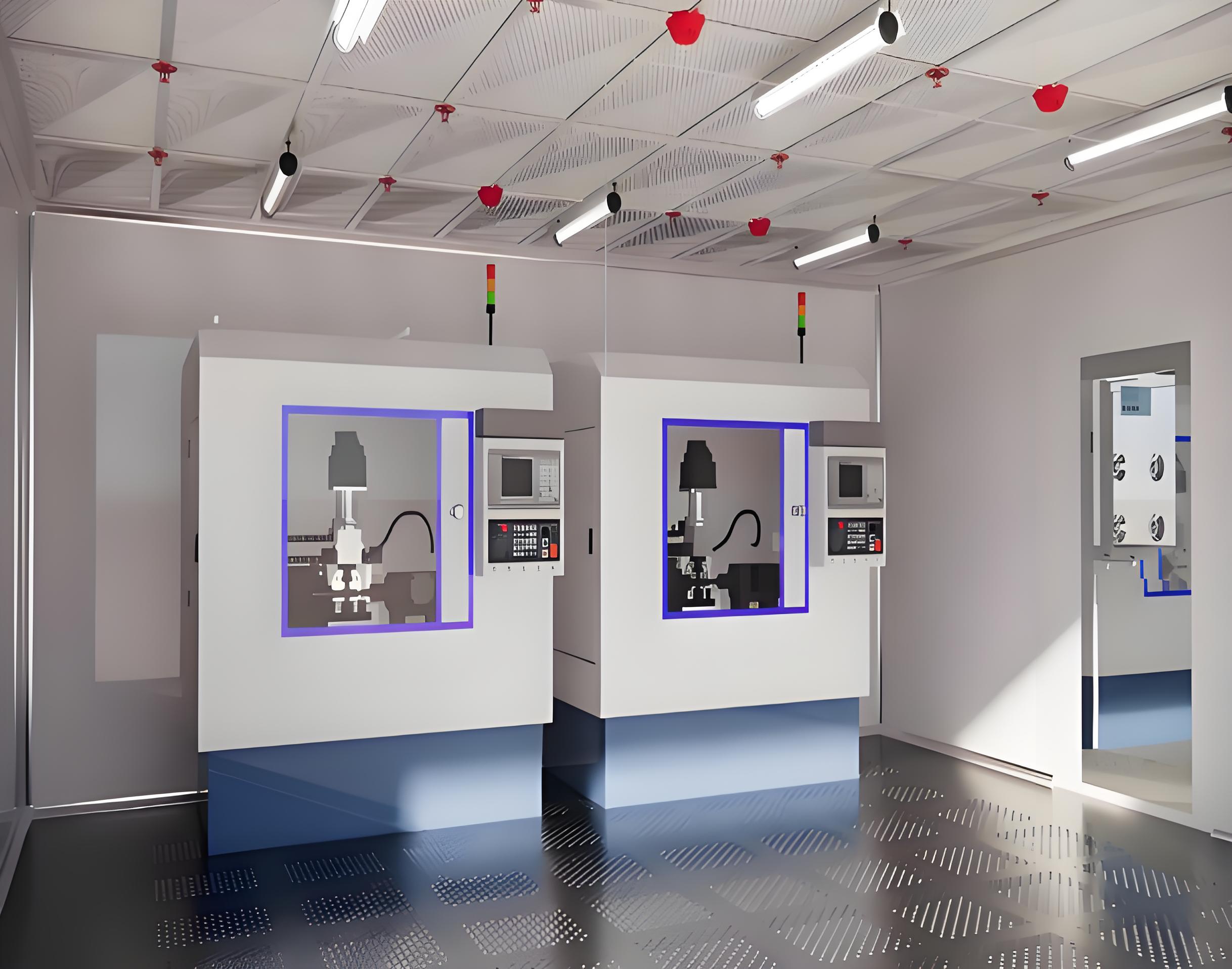
Microelectronics cleanroom design prioritizes vibration control and airborne molecular contamination (AMC) management. Structural isolation from building vibrations is achieved through slab isolation trenches or specialized foundation designs. AMC filtration, using chemically treated activated carbon filters, is integrated into the make-up air handling units. For 300 mm wafer fabs, the cleanroom design must also incorporate minienvironments—sealed enclosures around process tools that maintain ISO Class 1 conditions within a larger ISO Class 5 ballroom.
Gene therapy manufacturing introduces unique cleanroom design challenges: multiple segregated processing suites to prevent cross-contamination between patient-specific products. Each suite requires independent HVAC systems with dedicated exhaust and HEPA filtration. The design must accommodate biosafety level (BSL) 2 or 3 containment, requiring anterooms with chemical showers and effluent decontamination systems. TAI JIE ER has executed multiple multi-suite facilities where the cleanroom design incorporated modular wall systems that allow future reconfiguration as production scales up.
HVAC accounts for 50–70% of a cleanroom’s operational energy consumption. A well-executed cleanroom design balances filtration requirements with energy efficiency through fan array technology and demand-based control.
Fan array vs. single large fans: Arrays of smaller fans (typically 8–12 units) provide N+1 redundancy and allow staging of airflow based on real-time demand. Facilities using fan arrays report 20–25% lower fan energy consumption compared to traditional single-fan systems.
HEPA/ULPA filter selection: For ISO Class 5 and above, HEPA filters (≥99.97% efficiency at 0.3 µm) are standard. For ISO Class 3–4, ULPA filters (≥99.999% efficiency at 0.12 µm) are required. The cleanroom design must include filter housing with gel seals or knife-edge seals to bypass leakage, which accounts for up to 15% of total particle ingress in poorly sealed systems.
Demand-controlled ventilation: Using particle counters and occupancy sensors to modulate air change rates during non-production hours can reduce energy consumption by 30–40% without compromising cleanliness upon restart. This approach requires careful integration into the building management system (BMS).
Water-cooled chilled beams have emerged as an energy-efficient alternative for cleanroom design in cooling-dominant climates. By separating sensible cooling from ventilation, they reduce the required air handling unit airflow by up to 50% while maintaining temperature uniformity.
Analysis of post-occupancy evaluations from 27 cleanroom projects reveals recurrent issues that originate in the design phase.
Inadequate material transfer workflows: Designs that fail to provide sufficient staging areas and transfer hatches force operators to make unnecessary movements between zones, increasing particle shedding. One facility saw a 40% reduction in viable particulate excursions after redesigning material flow paths to minimize cross-zone transfers.
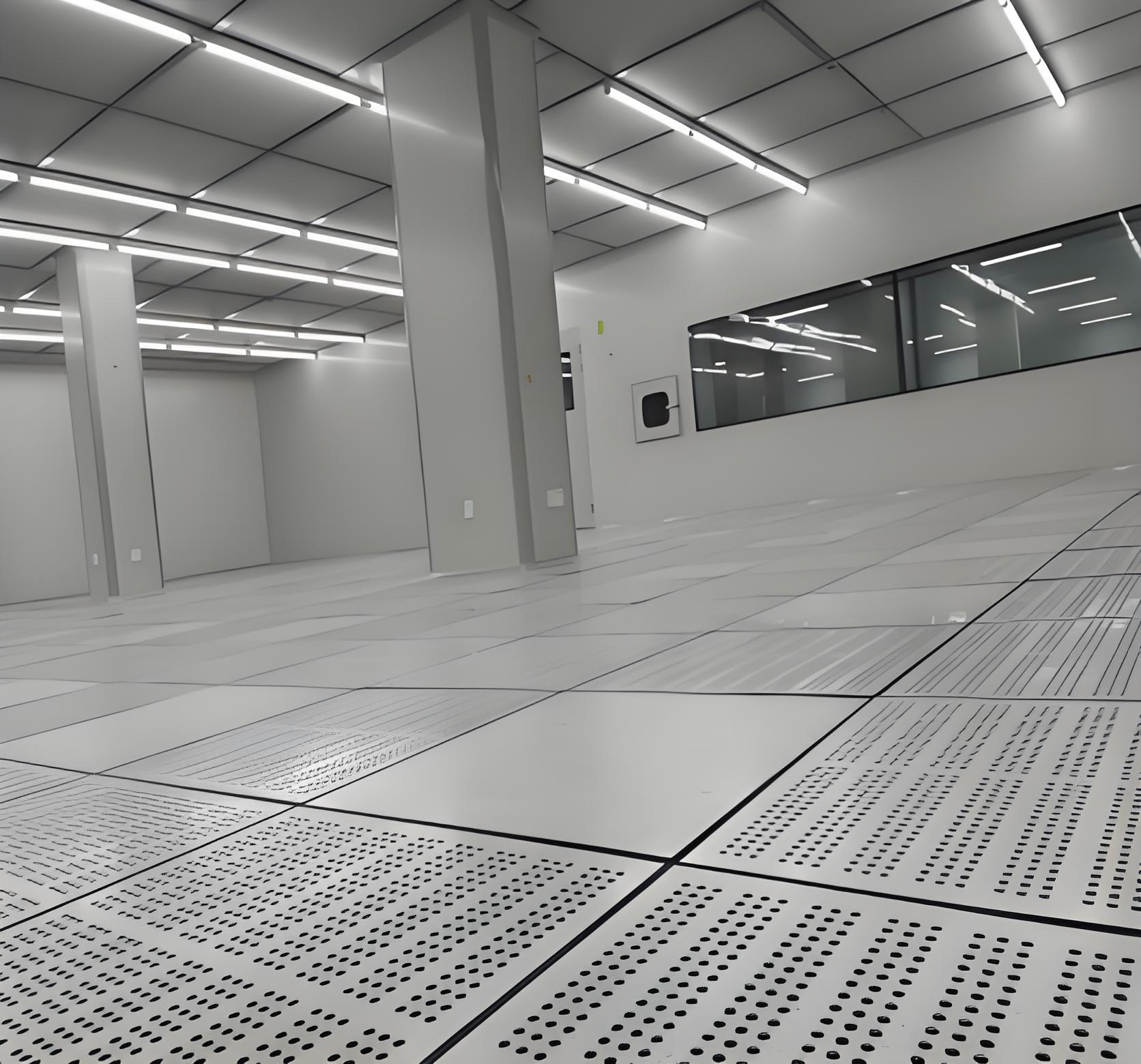
Thermal stratification in large-volume spaces: In ballroom-style cleanrooms, temperature gradients exceeding 2°C between floor and ceiling can induce convection currents that disrupt unidirectional flow. Proper cleanroom design incorporates computational modeling to optimize supply diffuser placement and return locations, often using perforated raised floors to achieve uniform thermal profiles.
Vibration from adjacent equipment: Vibration-sensitive processes (e.g., electron microscopy, lithography) require isolation. Design-stage vibration surveys and structural modeling are essential. A leading semiconductor manufacturer avoided $12 million in retrofitting costs by incorporating tuned mass dampers into the initial cleanroom design.
Modular construction has transformed cleanroom design by reducing on-site labor and enabling rapid reconfiguration. Prefabricated wall, ceiling, and floor cassettes are manufactured in controlled factory environments, eliminating weather-related delays and ensuring consistent joint sealing.
Speed: Modular cleanroom design reduces construction schedules by 30–50% compared to stick-built methods.
Reconfigurability: Systems with demountable panels allow facilities to adapt to new processes without demolition. A biotech client of TAI JIE ER reconfigured a 600 m² ISO Class 7 space into two separate ISO Class 6 suites in under three weeks using modular components.
Quality assurance: Factory-tested panels reduce the risk of field-installed sealant failures, a leading cause of particle leakage in conventional construction.
Modular approaches do require rigorous interface coordination between structural supports, MEP (mechanical, electrical, plumbing) systems, and the building envelope. Successful modular cleanroom design relies on BIM (Building Information Modeling) Level 300 or higher to resolve clashes before fabrication.
Design intent must be translated into documented performance. The commissioning process for cleanroom design includes:
Installation qualification (IQ): Verification that materials, components, and systems are installed per specifications. For HVAC systems, this includes filter integrity testing (using photometer scanning) and duct leakage testing (≤2% of design airflow).
Operational qualification (OQ): Testing under dynamic conditions—air change rates, pressure differentials, temperature, humidity, and particle counts—across all operational states (production, idle, alarm).
Performance qualification (PQ): Three-phase testing over a defined period to demonstrate consistent performance. Data from PQ establishes baseline for ongoing monitoring.
Regulatory bodies increasingly require continuous monitoring systems that record particle counts, differential pressure, and temperature/humidity at defined intervals. Cleanroom design must allocate space and access for these sensors, ensuring they do not disrupt airflow or create contamination points.
The next generation of cleanroom design incorporates sustainability metrics and digital operational models. Low-carbon materials, such as recycled aluminum panels and bio-based insulation foams, are being qualified for ISO Class 5–7 spaces. Energy recovery wheels with desiccant coatings reduce conditioning loads for outdoor air by 60–70% in humid climates.
Digital twins—real-time virtual replicas of the cleanroom—are becoming standard for complex facilities. They integrate sensor data with CFD models to predict contamination events before they occur. One pharmaceutical company using a digital twin reduced HVAC energy use by 22% while maintaining ISO Class 5 conditions through predictive control algorithms that anticipate filter loading and occupancy changes.
Effective cleanroom design is neither a generic architectural exercise nor a mere application of standards. It is a synthesis of process requirements, contamination control science, and mechanical engineering rigor. Facilities that engage specialist designers early—integrating process flows, HVAC dynamics, and modular construction strategies—achieve lower lifecycle costs, faster regulatory approvals, and greater operational flexibility. For organizations seeking validated, performance-based cleanroom design, TAI JIE ER delivers engineering solutions backed by comprehensive commissioning documentation and post-occupancy support.
A1: The initial step is a process risk assessment that defines the required ISO class or GMP grade for each operational zone, based on product exposure risk. This is followed by a user requirement specification (URS) that details airflow patterns, pressure cascades, material flows, and cleaning protocols. CFD modeling should be conducted before finalizing HVAC layout. Regulatory path (FDA, EMA, etc.) must be identified to align design documentation with submission requirements.
A2: ISO 14644-4 provides guidance but does not mandate specific air change rates. For ISO Class 7 (Grade C), typical values range from 20 to 40 air changes per hour. The precise rate is determined by factors such as: heat load from equipment, number of personnel, particle generation rates, and desired recovery time (typically ≤15 minutes from idle to operational state). Energy modeling should be performed to optimize the balance between cleanliness assurance and operating cost.
A3: Sterile injectable facilities require ISO Class 5 (Grade A) zones with unidirectional airflow, isolators or RABS, and stringent pressure cascades to prevent ingress of non-sterile air. OSD manufacturing typically operates at ISO Class 7 or 8, with emphasis on dust containment and explosion protection (ATEX zones) rather than sterility. OSD cleanroom design focuses on high-efficiency dust collection systems, segregated containment suites for potent compounds, and robust cleaning validation surfaces.
A4: Yes, but with strict segregation. Energy recovery wheels can be used if they are located in the exhaust airstream of non-hazardous areas and incorporate purge sections to prevent carryover. For facilities handling potent compounds or biological agents, run-around coils or plate heat exchangers are preferred because they maintain physical separation between supply and exhaust airstreams. Any energy recovery system must be validated for leakage (≤0.05% cross-contamination) per ANSI/ASHRAE Standard 84.
A5: Comprehensive documentation includes: design qualification (DQ) report detailing compliance with ISO 14644, GMP, and applicable codes; detailed engineering drawings (P&IDs, HVAC layouts, reflected ceiling plans); material certifications (fire rating, surface roughness, chemical resistance); validation master plan; and commissioning protocols (IQ/OQ). For modular systems, factory acceptance test (FAT) reports and shipping/installation verification are required. TAI JIE ER provides a fully documented package aligning with ASTM E2500 and ISPE baseline guides.


