Industrial environments producing sterile pharmaceuticals, semiconductor wafers, or medical devices require a built environment where particle concentration is rigorously managed. Cleanroom design goes beyond HEPA filters—it encompasses room geometry, surface finish specification, personnel flow, and differential pressure cascades. A properly engineered cleanroom minimizes contamination risks that lead to batch rejection (costing up to $2 million per hour for biotech facilities) or device failure. This article dissects the engineering parameters, material selections, and validation protocols that define professional cleanroom design, referencing ISO 14644-1:2015, EU GMP Annex 1, and IEST-RP-CC012.2 standards.
Every cleanroom design starts with determining the required ISO class. ISO 8 (Class 100,000) needs 15-20 air changes per hour (ACH), while ISO 5 (Class 100) requires 400-600 ACH with unidirectional flow. The airflow pattern—turbulent diluting or laminar sweeping—is dictated by process sensitivity. For aseptic filling lines, vertical laminar flow at 0.45 m/s ±20% ensures particle displacement. However, static dissipative requirements in electronics assembly may demand horizontal flow with raised floors. Computational fluid dynamics (CFD) modeling is now standard for validating that dead zones (air velocity <0.1 m/s) are eliminated. Failure to model these zones results in particle hotspots, directly impacting yield.
Differential pressure (DP) between adjacent rooms prevents cross-contamination. A typical pharmaceutical cleanroom design maintains a cascade: secondary corridor (0 Pa), gowning room (+15 Pa relative to external), ISO 7 cleanroom (+25 Pa), and ISO 5 filling zone (+35 Pa). DP monitoring with audible alarms for ±2 Pa deviation is mandatory. For potent compound handling, negative pressure relative to surrounding areas (e.g., -20 Pa) with 100% exhausted air is required. The design must incorporate pressure-relief dampers to avoid door operation forces exceeding 8 lbf. Seamless integration of DP sensors into building management systems (BMS) is a key deliverable in turnkey projects.
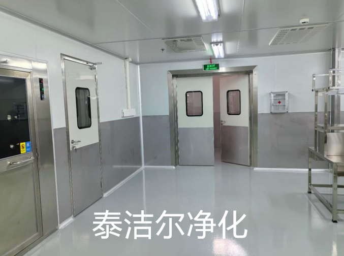
Wall panels: pharmaceutical-grade modular panels with a high-density polyurethane core (minimum 48 kg/m³) and coated steel skin (epoxy-polyester hybrid, 80-100 microns thickness). Flooring: conductive vinyl (10⁶–10⁹ ohms) for electronics, or seamless epoxy terrazzo for wet chemical areas. Ceilings: gasketed aluminum grid system supporting walkable access panels (load rating 200 kg). Coving radius must be ≥12 mm at wall-floor junctions. Sealants: silicone-based, low-VOC (<50 g/L) with elongation recovery ≥300% per ASTM D412. Cleanroom design documentation must include material certification for outgassing (ASTM E595) and microbial resistance (ISO 846).
For semiconductor fabs (ISO 3 to ISO 5), vibration control is paramount. Cleanroom design incorporates a separate structural slab isolated from building columns—using pneumatic isolators achieving ≤3 µm/s vibration velocity. Mini-environment systems (SMIF or FOUP) are integrated into the facility, requiring pass-through ports with interlocked doors. Airborne molecular contamination (AMC) filters (activated carbon and chemisorption media) are installed in recirculating air units to remove organics, acids, and bases. Static control extends to all flooring, workbenches, and storage racks, bonded to a common ground grid (<1 ohm resistance). The design also includes nitrogen-purged utility chases for gas lines.
EU GMP Annex 1 mandates Grade A (ISO 5) for critical zones, typically achieved by RABS (restricted access barrier systems) or isolators. Cleanroom design for these suites specifies raked ceilings (≥7° slope) to prevent condensate drip, flush-mounted luminaries, and seamless cove junctions. Wall penetrations for glove ports and transfer hatches are pre-formed with stainless steel collars and double O-rings. Material airlocks feature timer-interlocked doors and HEPA-filtered supply air. For cell and gene therapy cleanrooms, decentralized HVAC zones with independent HEPA filter banks enable one suite to remain operational while another undergoes decontamination with vaporized hydrogen peroxide (VHP).
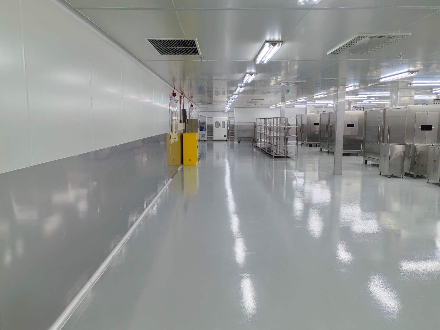
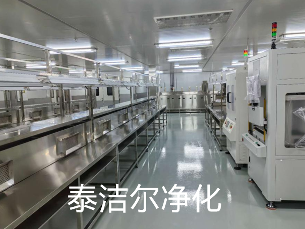
ISO 7 or ISO 8 environments with emphasis on particle control and antimicrobial surfaces. Cleanroom design in this sector prioritizes hygienic furniture—316L stainless steel with continuous welds and no sharp corners. Wall-mounted utility columns (electric, vacuum, compressed air) reduce floor clutter. Anteroom design includes sticky mats or automatic boot washers. The floor plan uses a "ballroom" layout (single large zone) rather than multiple small rooms to improve material flow efficiency. ESD properties are required when assembling PCB-based devices, with floor resistance tested per ANSI/ESD STM7.1 every six months.
Standard perforated ceiling tiles cause localized high-velocity jets and low-pressure recirculation zones. Solution: install thin-profile laminar flow diffusers (scrim sheets) with 0.5% open area and honeycomb straighteners. For vertical flow, the return air plenum must be located at low-level perimeter walls rather than through raised floor grilles directly below process equipment—this avoids turbulent wake formation downstream of machinery. CFD simulations should show a velocity uniformity ratio ≥0.9 across the working plane at 1 meter above finished floor.
Recirculating massive air volumes leads to fan energy costs representing 40-50% of cleanroom operational expenses. Mitigation strategies: use EC (electronically commutated) fan arrays with variable frequency drives, and incorporate run-around coils for heat recovery between exhaust and supply airstreams. Design the return air system with low-pressure-drop HEPA housings (initial ΔP ≤120 Pa). Also, zone the cleanroom so that non-critical areas (ISO 8 gowning) have lower ACH (20 ACH) while the core process zone (ISO 6 or 5) operates at required rates. A well-executed cleanroom design can reduce annual HVAC energy use by 30% compared to unoptimized designs.
Large process equipment (autoclaves, bioreactors) requires periodic servicing inside the cleanroom. The design solution is to place such equipment against external walls with sealed pass-through panels. Alternatively, specify modular wall sections that can be removed from the service corridor side. All maintenance doors into the clean zone must have interlocked alarms and HEPA-filtered air curtains. The design documentation should include a contamination control plan (CCP) detailing acceptable work practices for unscheduled interventions, including reclassification and recovery time testing.
Once construction is complete, a cleanroom design must undergo rigorous testing per ISO 14644-3. Required tests include: 1) Airborne particle count at rest and operational states (using isokinetic probes). 2) Air pressure difference measurement across all doors. 3) Airflow velocity and uniformity (for unidirectional systems). 4) HEPA filter integrity scanning (PAO or DEHS aerosol challenge, ≤0.01% penetration). 5) Recovery test: generate a 100-times higher particle concentration and measure time to return to specified class (typically 15-20 minutes for ISO 7). 6) Airflow visualization using smoke or dry ice to confirm unidirectional patterns. 7) Temperature and humidity mapping (≤ ±1°C, ≤ ±5% RH uniformity). The certification report must be renewed annually or after any modification to the HVAC or room envelope.
For turnkey delivery, TAI JIE ER integrates these validation steps into the project timeline. We provide a two-day FAT (factory acceptance test) on modular panels and a six-day SAT (site acceptance test) covering all 14644-3 parameters. Our in-house microbiologists also conduct surface viable sampling (contact plates on walls and floors) for GMP projects, ensuring microbial contamination remains within action limits.
Emerging requirements include modular cleanrooms for personalized medicine where layouts change every 6-12 months. Cleanroom design now employs demountable partition systems with cam-lock joints and reusable seal gaskets, allowing reconfiguration with ≤5% material waste. Another trend is the use of photocatalytic titanium dioxide coatings on surfaces—under UV-A light, TiO₂ generates reactive oxygen species that degrade organic residues, reducing cleaning frequency. However, this must be validated for non-shedding properties. For next-generation battery dry rooms (dew point ≤ -50°C), cleanroom design incorporates rotary desiccant dehumidifiers with enthalpy wheels, and double-wall panels with vapor barriers (10⁻¹² g/m·s·Pa).
A collaboration with TAI JIE ER ensures that your cleanroom design addresses not only current production needs but also scalable ISO class adjustments. Our prefabricated systems include integrated utility chases and spare HEPA housing slots, reducing future retrofit costs by up to 40%.
Q1: What is the typical cost per square foot for a turnkey ISO 7
cleanroom design and construction?
A1: For modular ISO 7 (Class
10,000) with standard HVAC, electrical, and hardwall panels, budgets range from
$350 to $550 per square foot in North America/Europe. This includes design
engineering, material certification, installation, and ISO 14644-3 validation.
For ISO 5 (Class 100) laminar flow suites, expect $750–$1,200 per square foot
due to increased ACH, raised-floor plenums, and larger HEPA banks. Costs can be
reduced by using softwall curtains for lower-grade areas, but this sacrifices
long-term durability for GMP applications.
Q2: How many air changes per hour (ACH) are required for an ISO 6
cleanroom?
A2: ISO 6 (Class 1,000) typically requires 90-180 ACH
with non-unidirectional airflow (turbulent mixing). However, if the process
demands unidirectional flow, the velocity must be 0.2–0.5 m/s, which usually
results in >300 ACH. The exact ACH is determined by the cleanroom’s recovery
test performance—installing more air changes than necessary increases cost
without added benefit. Always base ACH on ISO 14644-4 design criteria plus a
safety factor of 20%.
Q3: What is the minimum ceiling height for a cleanroom design that
includes a laminar flow array?
A3: For vertical laminar flow, the
distance from the filter face to the working surface should be between 1.5 and
2.4 meters to maintain uniform velocity of 0.45 m/s ±20%. Therefore, the
finished ceiling height must be at least 2.6 meters (allowing 200mm for HEPA
housing and diffuser). For service plenum above ceiling, add 500-800mm. The
total structural height should be 3.1–3.4 meters. For non-unidirectional
cleanrooms, 2.4 meters is acceptable but must verify that smoke testing shows no
stagnant zones near high obstructions.
Q4: Can an existing conventional warehouse be converted into an ISO 8
cleanroom through simple 'cleanroom design' modifications?
A4:
Partial conversion is possible but requires significant work. The existing walls
and roof need to be sealed for leakage (≤0.05 CFM per square foot at 75 Pa). The
floor must be ground and coated with epoxy-polyurethane (300-500 microns).
Ceiling grid with HEPA fan filter units (FFUs) can be suspended from the
existing structure. However, the HVAC must be isolated or supplemented with HEPA
recirculation units. A professional cleanroom design for retrofits includes a
pre-conversion air tightness test and seismic bracing assessment. For a 500 sq.
ft. ISO 8, retrofit costs roughly $150–250 per square foot—less than new build
but still substantial.
Q5: How does cleanroom design address noise levels for operator
comfort and safety?
A5: ISO 14644-5 recommends noise limits: ≤65 dBA
for unidirectional cleanrooms and ≤60 dBA for turbulent areas. To achieve this,
designers specify low-pressure-drop fan arrays (max 1.5 in H₂O), silencers on
return air ducts, and acoustical linings on air plenums (but only non-shedding
materials like mineral fiber with encapsulating paint). Vibration isolation
mounts (steel spring isolators with 90% efficiency) decouple fan motors from
ceiling grid. For extremely quiet areas (e.g., electron microscopy cleanrooms),
the cleanroom design may relocate FFU motors into a separate mechanical
mezzanine with ducted supply.
Q6: What documentation is required for a validated cleanroom design
in a regulated pharmaceutical facility?
A6: You need a User
Requirement Specification (URS), a Design Qualification (DQ) with as-built
drawings, an Installation Qualification (IQ) covering material receipts and
component verification, an Operational Qualification (OQ) for all alarms and
interlocks, and a Performance Qualification (PQ) consisting of three consecutive
days of particle and microbial sampling. Also required: Standard Operating
Procedures (SOPs) for gowning, cleaning, and maintenance. TAI JIE ER supplies a complete validation package including FAT/SAT protocols and
traceability matrix for every sealed joint.
Selecting the wrong ISO class or airflow pattern leads to production delays and regulatory observations. Our engineering team at TAI JIE ER provides a free initial layout review and particle source assessment. Send your process flow diagram and cleanroom area requirements to receive a preliminary design concept with CFD simulation snapshots and material budget. We support projects from ISO 8 to ISO 3, with turnkey delivery including validation and operator training.
Send your inquiry to 912228126@qq.com or complete the technical specification form on our website. All responses include a non-disclosure agreement (NDA) and a portfolio of similar-class installations.


