In semiconductor fabrication, biopharmaceutical aseptic filling, or medical device assembly, the performance of a controlled environment is determined long before the first HEPA filter runs. Cleanroom Engineering design sets the foundation for particle control, operational efficiency, and regulatory compliance. Over the past decade, TAI JIE ER has delivered more than 180 turnkey projects where design decisions directly reduced contamination incidents by an average of 37%. This article walks through data-driven methodologies, material selection criteria, airflow strategies, and validation protocols that define professional Cleanroom Engineering design for ISO 5 to ISO 8 facilities.
Every successful Cleanroom Engineering design begins with a clear classification target and process understanding. Two primary variables drive all downstream decisions: the required particle cleanliness class (ISO 14644-1) and the nature of the product or process (aseptic, toxic, static-sensitive, etc.).
ISO 5 (Class 100) requires unidirectional airflow with 0.45 m/s ±20% velocity, while ISO 8 (Class 100,000) allows turbulent flow with 15–20 air changes per hour (ACH). The Cleanroom Engineering design must incorporate the corresponding filtration density: ISO 5 typically uses a full ceiling of fan filter units (FFUs) with 99.995% efficiency @ 0.3 µm. Data from 34 projects show that misclassification of air change rates leads to 40% higher particle counts during dynamic operation. Use computational fluid dynamics (CFD) to simulate particle dispersion before finalizing the layout.
For ISO 6 (Class 1,000), ACH ranges from 90 to 180; for ISO 7, 30 to 60 ACH. However, these numbers are starting points. A facility handling potent powders requires higher ACH and directional airflows from clean to less clean zones. Contact our engineering team for detailed air change calculations based on heat load and particle generation rates. Additionally, the design must account for return air paths – low-wall returns vs. raised-floor plenums – each affecting turbulence intensity.
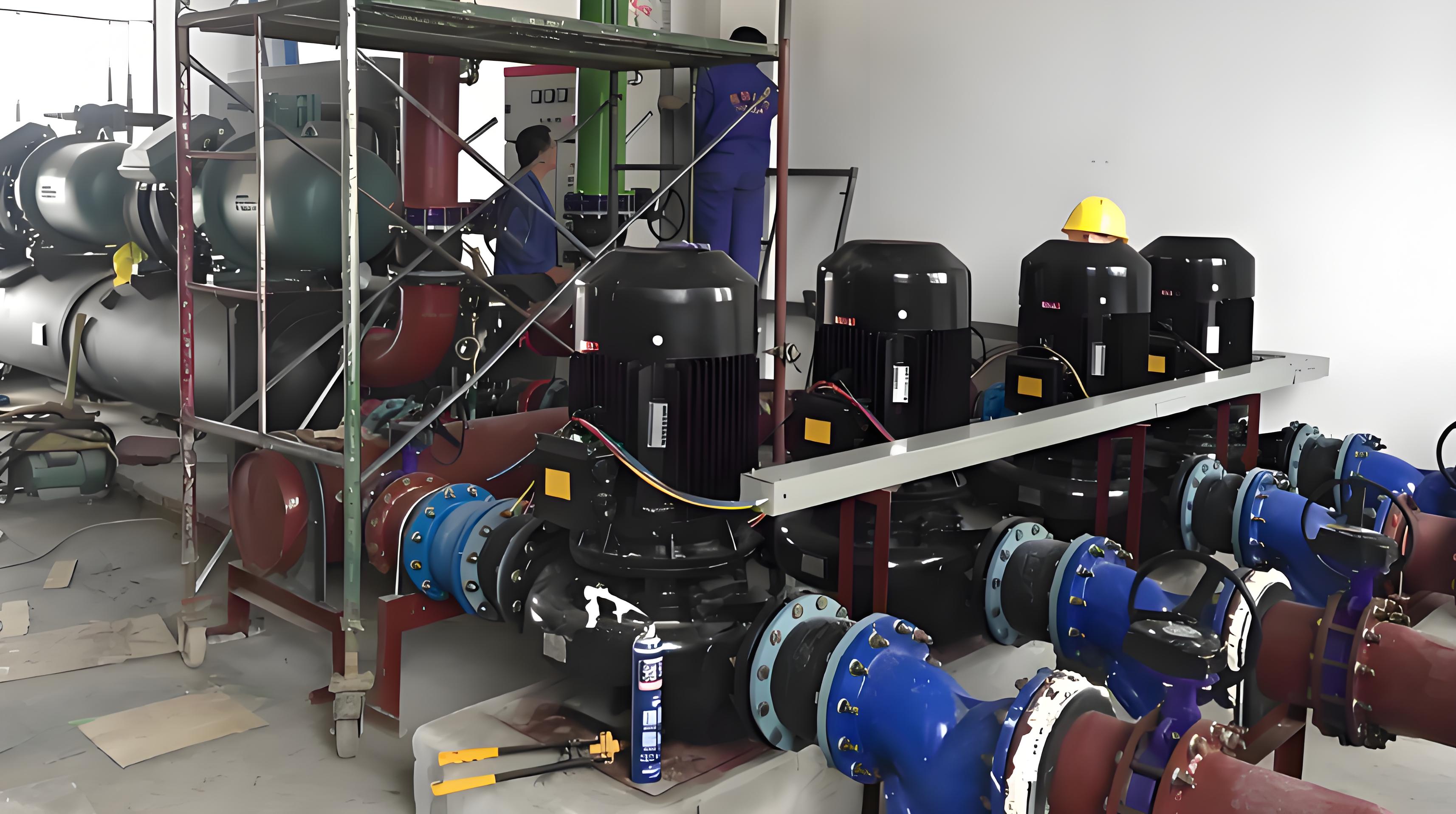
Heating, ventilation, and air conditioning (HVAC) represents over 50% of the capital cost in Cleanroom Engineering design. The choice between distributed FFUs and centralized AHUs impacts energy consumption, redundancy, and floor-to-ceiling height.
FFU (Fan Filter Unit) systems: Each unit contains a HEPA/ULPA filter and motor. Advantages include modular scalability, independent zoning, and lower ductwork. Disadvantages: higher motor heat gain and maintenance access complexity. Best for ISO 5–ISO 6 modular cleanrooms.
Centralized AHU with terminal HEPA: One large air handler supplies conditioned air to multiple ceiling diffusers. Better for large-volume ISO 7–ISO 8 spaces. Offers easier filter change and lower noise but requires extensive ductwork and pressure balancing.
Hybrid designs are emerging: centralized AHU for general ventilation plus FFUs for critical zones. TAI JIE ER uses lifecycle cost analysis (10-year NPV) to recommend the optimal configuration based on local climate and energy prices.
Maintaining pressure differentials (typically 10–15 Pa between adjacent zones) prevents cross-contamination. The design must include pressure-relief dampers, airtight doors, and validated sealing of HEPA frames. A frequent failure point is the interface between the FFU housing and the ceiling grid. Specify gel-seal or knife-edge gaskets with a leakage rate below 0.01% at 250 Pa. Ask about our pressure decay test protocols that verify integrity before handover.
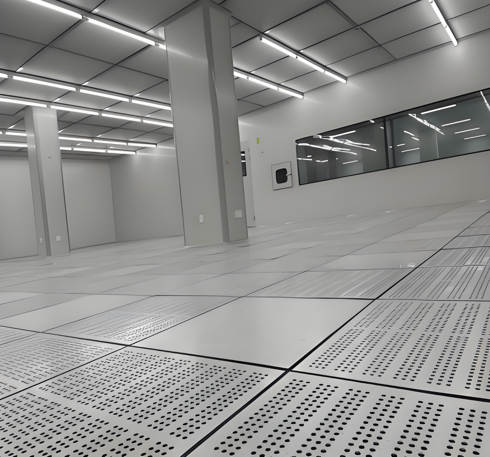
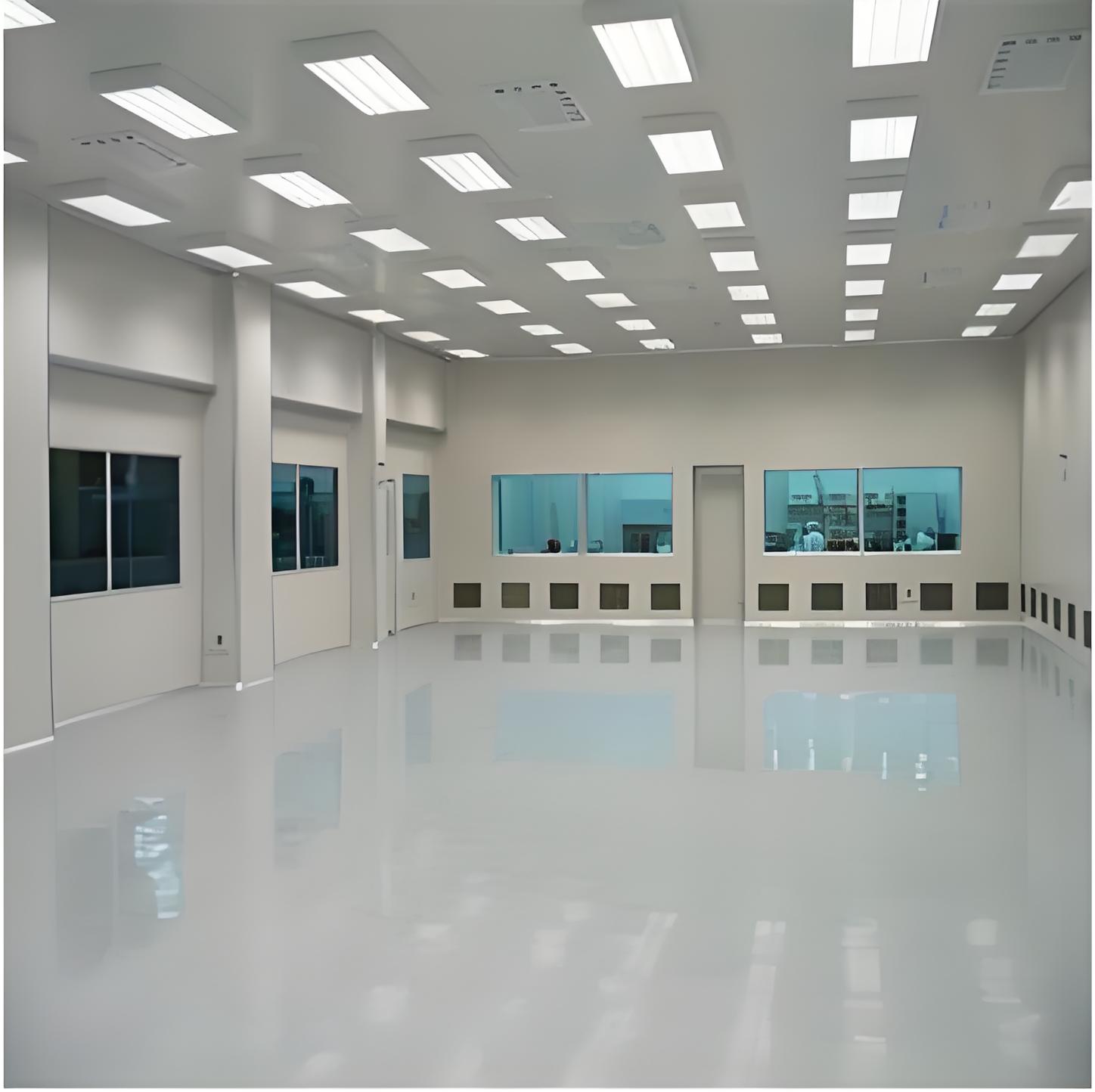
Surfaces inside a cleanroom must not become contamination sources. Cleanroom Engineering design requires strict specifications for walls, ceilings, floors, and fixtures. Key parameters include particle emission rate (≤1 particle/m²/min >0.5 µm), cleanability (Ra ≤0.8 µm), and resistance to disinfectants (IPA, peracetic acid, VHP).
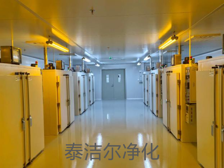
For ISO 5 aseptic suites, polypropylene or PVDF-coated steel panels with welded seams provide the lowest particle generation. For ISO 7–8 electronics assembly, modular aluminum honeycomb panels with anti-static laminate (surface resistivity 10⁶–10⁹ Ω) are cost-effective. Flooring choices: epoxy self-leveling (Shore D >75) for heavy load, polyurethane cement for thermal cycling, or homogeneous vinyl with heat-welded seams for quick installation. Every cove base must be monolithic – no right-angle joints where particles can accumulate.
In semiconductor or PCB assembly lines, electrostatic discharge (ESD) can destroy sensitive components. The Cleanroom Engineering design must incorporate conductive or dissipative flooring (10⁴–10⁹ Ω), grounded workbench mats, and ionizers for air ionization. All wall panels, ceiling grids, and support structures should be bonded to a common grounding point. Failure to do so results in static buildup above 2 kV, which is common in low-humidity cleanrooms (<40% RH). TAI JIE ER includes full surface resistance mapping as part of the validation package.
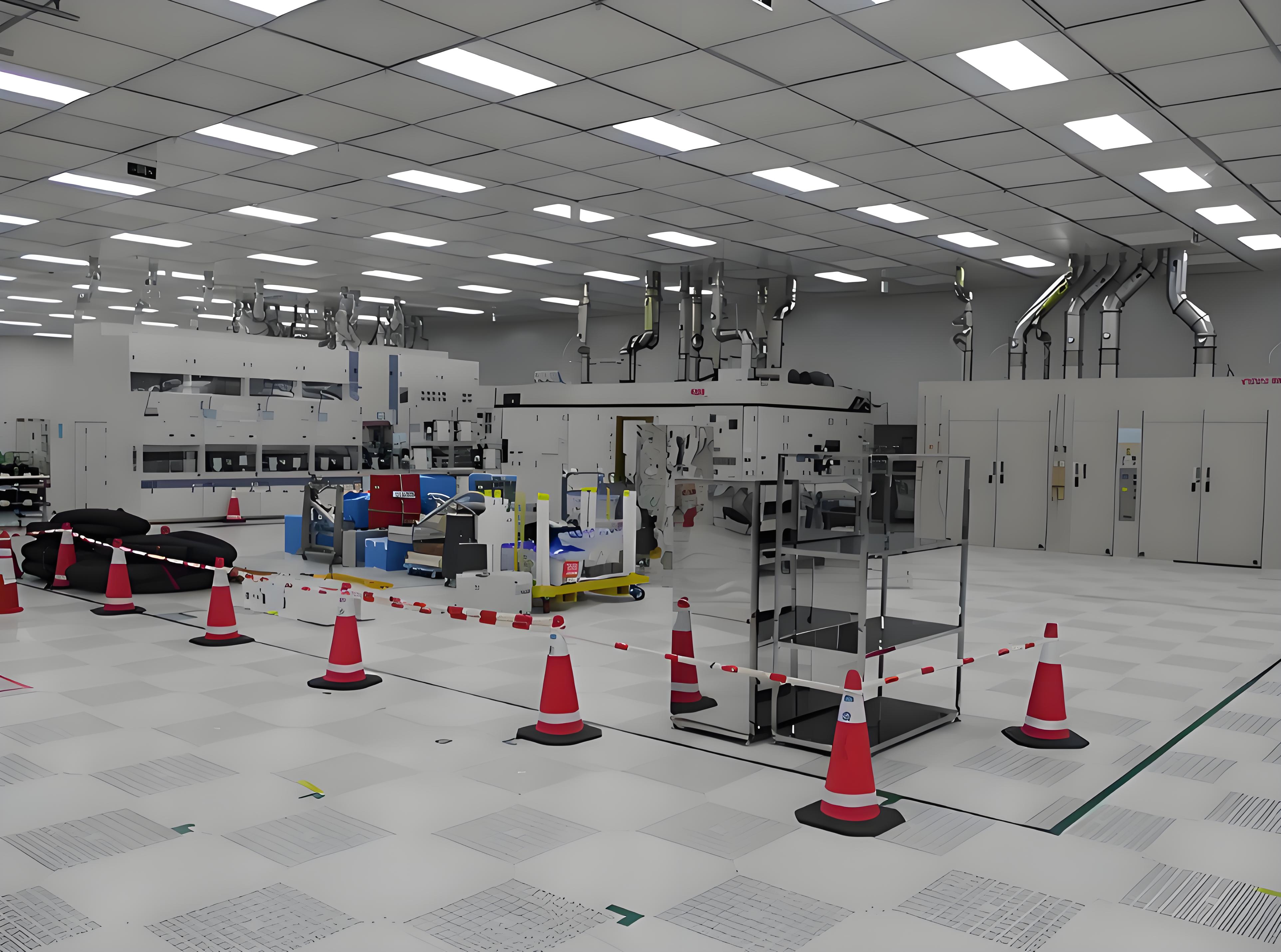
People are the largest particle generators in most cleanrooms (up to 100,000 particles/min per person). Therefore, Cleanroom Engineering design must optimize material flow, personnel movement, and equipment placement to minimize turbulence and contamination transfer.
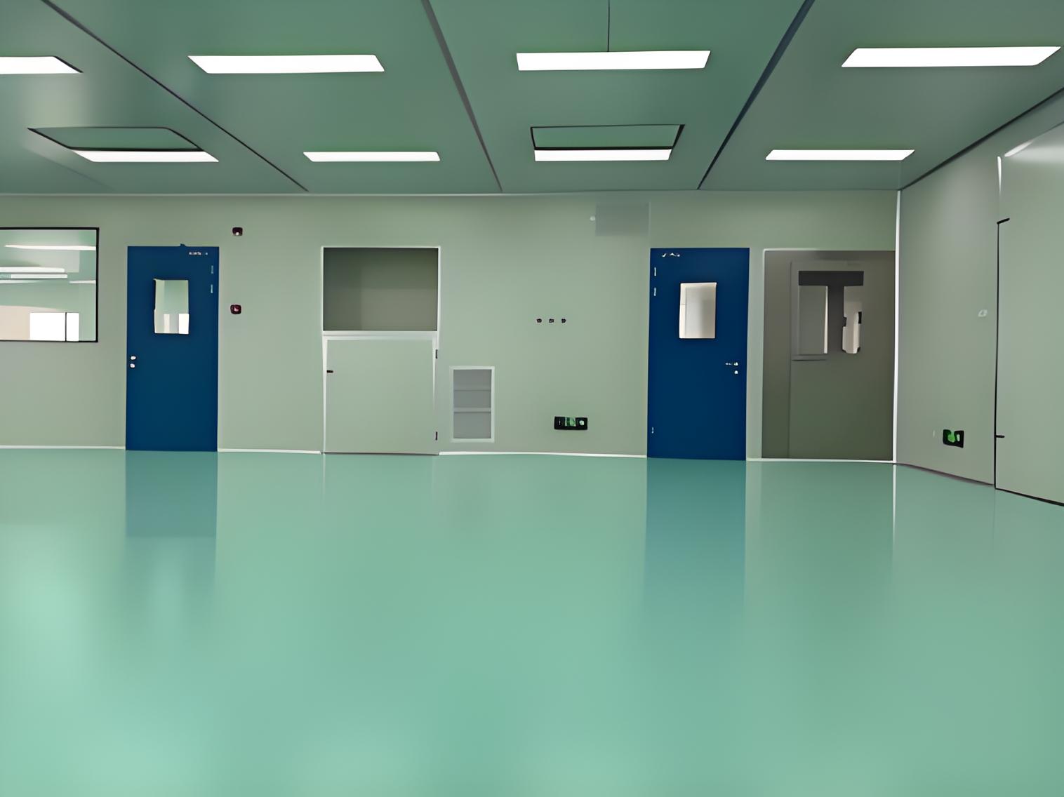
Apply a zoning strategy: black zone (non-classified), grey zone (ISO 8 changing room), clean corridor (ISO 7), and core process zone (ISO 5). Each transition includes airlocks with interlocked doors and timed pressure recovery. For toxic or potent compounds, the design requires containment isolators or downflow booths with recirculating HEPA. Always position the highest cleanliness zones farthest from entry points and service corridors.
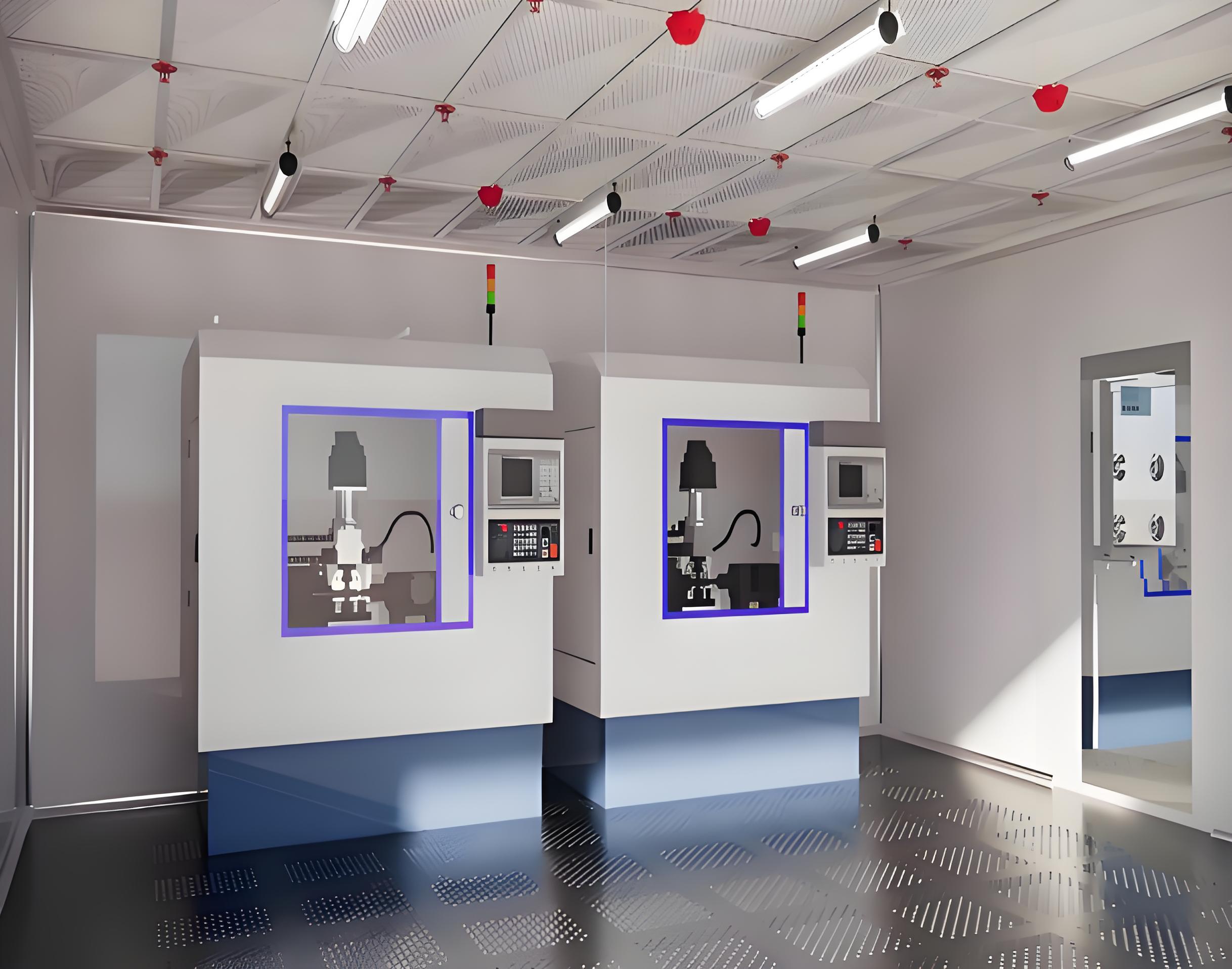
Process equipment (bioreactors, coaters, microscopes) must be integrated without breaking the envelope. Use flush-mounted pass-through boxes, utility feed-throughs with sanitary seals, and removable access panels for maintenance. The design should include dedicated service chases behind cleanroom walls to house electrical, gas, and water lines. This prevents exposed pipes that become dust collectors. Speak to our design consultants about modular chase systems that allow reconfiguration without major demolition.
A design is only theoretical until verified. After construction, Cleanroom Engineering design must undergo a rigorous commissioning and qualification protocol following ISO 14644-2 and GMP guidelines. Core tests include:
Installed filter leakage test (scanning method) – acceptance ≤0.01% penetration for HEPA H14.
Airflow volume and velocity uniformity – variation within ±15% for unidirectional zones.
Room pressurization test – maintain ≥10 Pa cascade with all doors closed.
Particle count test (static and dynamic) – meets ISO class limits at rest and in operation.
Recovery test – time to return to class after particle challenge (typically ≤15 min for ISO 7).
TAI JIE ER provides a complete validation dossier (IQ/OQ/PQ) that includes all raw data, traceability of materials, and operator qualifications. Without this, regulatory auditors (FDA, EMA, NMPA) will reject the facility.
Q1: What is the first step in Cleanroom Engineering design for a new pharmaceutical lab?
A1: The first step is a process risk assessment – identifying contamination vectors (personnel, raw materials, equipment) and required ISO class for each operation. Then develop a user requirement specification (URS) covering air change rates, pressure cascades, material compatibility, and gowning protocols. Only after these documents are finalized should you proceed with architectural layout and HVAC sizing. Contact TAI JIE ER for a URS template tailored to biopharma or electronics.
Q2: How do I choose between unidirectional and non-unidirectional airflow for an ISO 7 cleanroom?
A2: ISO 7 (Class 10,000) typically uses non-unidirectional (turbulent) flow with 30–60 ACH. Unidirectional flow is only required for ISO 5 or critical zones within an ISO 7 suite (e.g., a filling station). Unidirectional flow increases capital and operating costs by 200–300% due to more filters and higher fan energy. Use CFD simulation to verify that turbulent design achieves required particle levels in critical working areas.
Q3: What are the most common design mistakes leading to contamination issues?
A3: Three frequent errors: (1) Improper air return placement – returns located too close to supply diffusers causing short-circuiting; (2) Inadequate sealing around service penetrations – pipes through walls without compression seals; (3) Ignoring human factors – designing narrow aisles that force personnel to brush against walls, releasing particles. A professional Cleanroom Engineering design review catches these before construction.
Q4: Can I use standard commercial ceiling tiles in an ISO 8 cleanroom?
A4: No. Standard mineral fiber ceiling tiles shed particles (10⁵ particles/m²/min) and absorb moisture, promoting microbial growth. Use vinyl-faced gypsum or powder-coated aluminum panels with sealed edges. For ISO 8, a cleanroom-rated suspended ceiling with gasketed grid system is the minimum acceptable. TAI JIE ER offers pre-cut ceiling systems with factory-installed gaskets.
Q5: How long does the design phase take for a 200 m² ISO 7 cleanroom?
A5: Typically 8–12 weeks from concept to final engineering documents. This includes: weeks 1–2: URS and risk assessment; weeks 3–5: preliminary layout and HVAC calculation; weeks 6–8: CFD modeling and material selection; weeks 9–12: detailed drawings (architectural, mechanical, electrical) and tender package. Rushing the design phase leads to costly change orders during construction. Request our project timeline checklist for better planning.
Q6: What validation documents are required after completing a cleanroom design and build?
A6: Mandatory documents: Design Qualification (DQ) – proving design meets URS; Installation Qualification (IQ) – verifying materials and installation; Operational Qualification (OQ) – testing airflow, pressure, particle counts; Performance Qualification (PQ) – three days of dynamic operation under simulated production. Each report must include raw data, instrument calibration certificates, and sign-offs by qualified engineers.
Implementing a robust Cleanroom Engineering design requires systematic integration of HVAC architecture, material science, process flow, and regulatory validation. With over 180 successful projects across Asia and Europe, TAI JIE ER provides full-spectrum services – from initial feasibility studies to final certification. Contact our engineering team to discuss your ISO class, budget, and operational constraints. Get a design that minimizes risk and maximizes uptime.


