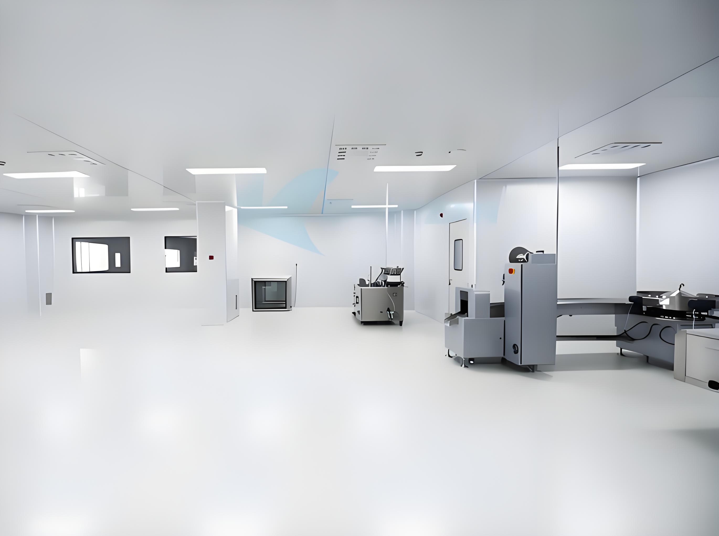
The foundation of any contamination-controlled facility lies in its cleanroom design. Whether for pharmaceutical aseptic processing, semiconductor lithography, or advanced medical device assembly, the design phase dictates long-term operational success, regulatory acceptance, and cost efficiency. This article provides a technical deep-dive into the core pillars that define a robust cleanroom design, leveraging decades of engineering experience and current ISO 14644 standards.
A compliant cleanroom design starts with the correct classification. ISO 14644‑1 defines classes from ISO 1 to ISO 9 based on airborne particle concentration. For GMP‑guided industries (EU Annex 1 or FDA), the design must also map these classes to operational states (at‑rest / in‑operation). The selection of the class—for example, ISO 5 for a filling line or ISO 7 for a background corridor—directly impacts air change rates, filter coverage, and pressurization cascades. TAI JIE ER’s engineering team always initiates projects with a gap analysis between the desired cleanroom class and the client’s process tolerance, ensuring that the cleanroom design meets both current and anticipated regulatory requirements.
HVAC constitutes the mechanical core of any cleanroom. Two primary airflow principles govern modern cleanroom design:
Unidirectional (laminar) airflow – used for ISO 5 and cleaner zones, with velocities typically 0.3–0.5 m/s ±20% (ISO 14644‑4).
Non‑unidirectional (turbulent) airflow – applied in ISO 6–8 rooms, relying on dilution via high air change rates (e.g., 60–90 ACH for ISO 7, 25–40 ACH for ISO 8).
HEPA/ULPA filters (efficiency ≥99.99% at MPPS) must be integrated with leaktight housings and gel‑seal frames to bypass bypass leakage. Computational Fluid Dynamics (CFD) modelling is now a standard tool to validate airflow patterns, especially in large‐scale cleanroom design projects, ensuring no stagnant zones exist near critical processes. TAI JIE ER employs CFD during the design phase to optimize diffuser placement and return air positions, reducing turbulence and particle entrapment.
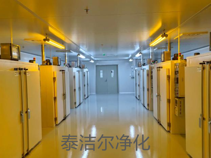
Material compatibility is often underestimated. In a cleanroom design, every surface must be non‑shedding, resistant to cleaning agents, and easy to decontaminate. Common choices include:
Walls and ceilings – powder‑coated steel or aluminium honeycomb panels with smooth, pinhole‑free finishes.
Flooring – seamless conductive or dissipative vinyl (resistance 10⁶–10⁹ Ω) to manage electrostatic discharge (ESD) in electronics cleanrooms.
Furniture – electropolished stainless steel (AISI 304/316L) with rounded corners (radius ≥3 mm) to eliminate microbial niches.
The choice of sealants (silicone or epoxy‑based) must comply with outgassing limits (ISO 14644‑8) and be resistant to repeated VHP (vaporized hydrogen peroxide) cycles in bio‑cleanrooms.
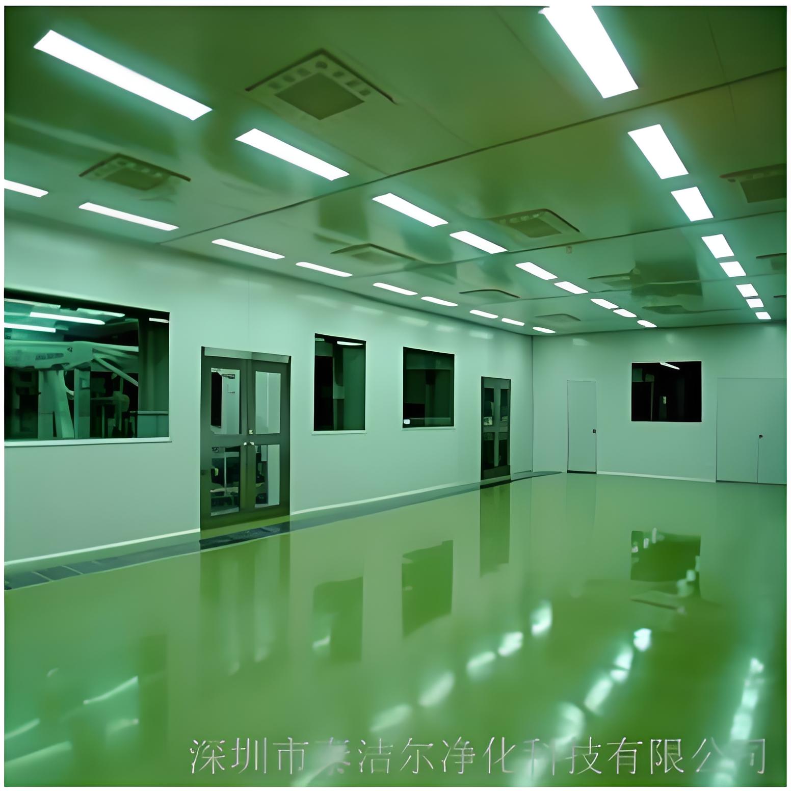
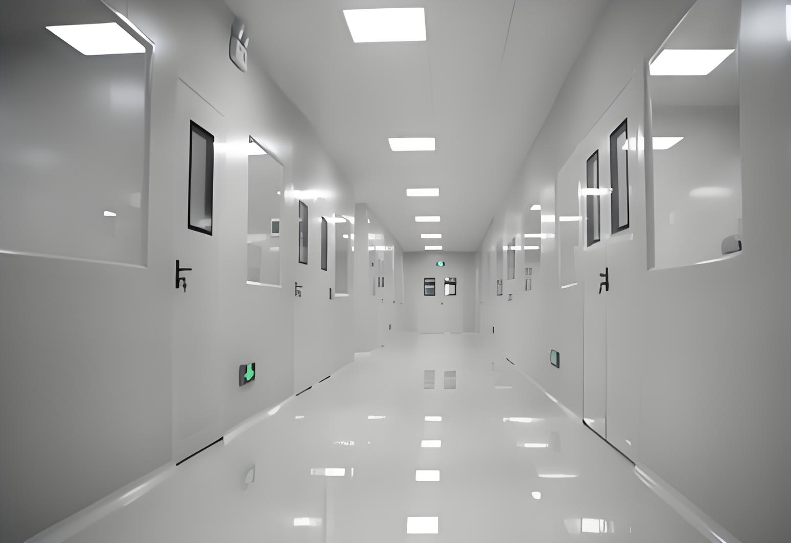
A functional cleanroom design minimizes contamination risks through intelligent spatial separation. Key considerations include:
Personnel and material flows – separate airlocks (with cascading pressure differentials of 10–15 Pa) and pass‑through chambers (with interlocking doors).
Clean / dirty corridor concepts – used in aseptic facilities to segregate waste from sterile components.
Buffer zones – gowning rooms must provide at least one class lower than the adjacent cleanroom; for ISO 5, the ante‑room is typically ISO 7.
Data from over 200 validated cleanrooms show that poor layout accounts for 60% of recurrent contamination incidents. Therefore, TAI JIE ER applies lean‑manufacturing principles (value stream mapping) during the architectural design to reduce unnecessary movement and cross‑contamination points.
Contemporary cleanroom design must balance contamination control with energy consumption. HVAC typically represents 60–80% of a cleanroom’s energy use. Strategies to reduce this footprint include:
Demand‑based ventilation – using particle sensors to modulate air changes during idle periods (allowed by ISO 14644‑4:2022).
High‑efficiency fan filter units (FFUs) with EC motors, saving up to 30% energy compared to AC types.
Heat recovery wheels and optimized chilling systems.
For semiconductor fabs, where cleanroom design includes high‑load process tools, water‑cooled utilities and separated make‑up air units (MAUs) with dry cooling coils are essential to maintain dew point control without excessive reheat.
Modular construction has evolved from temporary solutions to a permanent, high‑performance option. A modular cleanroom design uses prefabricated panels with integrated utility chases, allowing rapid reconfiguration. Advantages include:
Reduced on‑site construction time (by 30–50%).
Lower risk of contamination during installation (panels are assembled clean in a controlled factory).
Ability to relocate or expand the cleanroom as production needs change.
TAI JIE ER specializes in hybrid designs that combine stick‑built shells with modular cleanroom pods, ensuring scalability without compromising on airtightness (tested to ≤0.5 % leakage at 250 Pa).
A well‑executed cleanroom design must be verifiable. The commissioning protocol (based on ISO 14644‑3) includes:
Airborne particle count tests – at‑rest and in‑operation for all classified zones.
Airflow velocity and uniformity measurements (for unidirectional zones).
Filter integrity scanning (PAO / DOP tests).
Pressure differential and recovery tests (e.g., recovery time ≤15 min for ISO 7).
Temperature and humidity mapping – typically 18–22 °C ±1 °C, RH 35–55 % depending on process.
After handover, continuous monitoring systems (CMS) with real‑time particle counters and differential pressure sensors are integrated into the cleanroom design to provide alarms and data integrity for regulatory audits.
Cleanroom design is a multidisciplinary endeavour that bridges mechanical engineering, architecture, process knowledge, and regulatory science. Cutting corners during the design phase leads to chronic operational problems—elevated particle counts, high energy bills, and failed audits. By partnering with an experienced engineering firm like TAI JIE ER, organizations ensure that their cleanroom design is future‑proof, compliant, and optimized for total cost of ownership. Whether you need a new ISO‑compliant facility or an upgrade of an existing area, rigorous design remains the single most critical factor for contamination control success.
Q1: What are the key differences between ISO 7 and ISO 8 cleanroom design?
A1: ISO 7 (Class 10,000) requires 60–90 air changes per hour (ACH) and typically uses full ceiling HEPA coverage with raised floors or low‑sidewall returns. ISO 8 (Class 100,000) operates at 25–40 ACH and can use turbulent mixing with ceiling‑mounted HEPA filters. The pressure differential to adjacent areas is usually ≥12.5 Pa for both, but ISO 7 often demands tighter temperature/humidity control (±1 °C vs. ±2 °C for ISO 8) due to more sensitive processes.
Q2: How often should HEPA filters be tested in a cleanroom?
A2: According to ISO 14644‑2, HEPA filter integrity testing (leak testing) should be performed at least every 6–12 months for critical zones (ISO 5 and lower). For ISO 6‑8, an annual test is standard. However, if the cleanroom design includes continuous particle monitoring, the interval may be extended based on risk assessment, but never beyond 24 months.
Q3: What is the minimum pressure differential required for a cleanroom?
A3: ISO 14644‑4 recommends a minimum pressure differential of 5–20 Pa between cleanrooms of different classes. In practice, 10–15 Pa is common to ensure airflow direction during door openings. For pharmaceutical GMP, the EU Annex 1 demands a minimum of 10 Pa between clean and less clean areas, and the cleanroom design must incorporate pressure alarms to detect deviations.
Q4: Can existing facilities be retrofitted with modular cleanroom design?
A4: Yes, modular cleanroom systems are ideal for retrofitting because they require minimal structural modification. Prefabricated panels can be assembled inside an existing shell, and utilities (electricity, gases, data) are routed through integrated service chases. TAI JIE ER has successfully completed numerous retrofits where production downtime was reduced by 40% compared to conventional construction.
Q5: How does cleanroom design impact energy consumption?
A5: A poorly optimized cleanroom design can double energy costs compared to an efficient one. Factors include fan static pressure (higher than necessary due to undersized ductwork), excessive air changes, and lack of heat recovery. Using CFD‑optimized layouts, low‑pressure‑drop HEPA filters, and variable‑speed drives typically reduces energy use by 25‑35% without compromising cleanliness.
Q6: What is the role of an ante‑room in cleanroom design?
A6: An ante‑room (or airlock) acts as a buffer between a controlled area and a less clean environment. Its purpose is to prevent contamination ingress during personnel or material transfer. In a proper cleanroom design, ante‑rooms are pressurized either positive or negative depending on the containment need, and they often include gowning benches, sticky mats, and HEPA filtered air showers to remove surface particles.
Q7: What are the most common mistakes in cleanroom design?
A7: The top three errors are: (1) under‑sizing HVAC capacity, leading to inability to recover cleanliness after interventions; (2) ignoring the microbiological load in bio‑cleanrooms (e.g., no consideration for condensate drains in cooling coils); (3) poor ergonomics that cause operators to touch surfaces unintentionally. Engaging a specialist like TAI JIE ER early in the project helps avoid these pitfalls through integrated process and architectural design.


