

Facilities for sterile manufacturing, microelectronics assembly, and biological research demand a controlled environment where airborne particle concentration, microbial load, and surface cleanliness are strictly managed. The foundational element is not equipment selection but the Cleanroom design — a holistic engineering framework integrating HVAC architecture, partition materials, pressure cascades, and human factors. Poorly conceived designs lead to recurrent contamination events, costly requalifications, and regulatory non-compliance. This article presents a technical walkthrough of validated Cleanroom design principles, combining ISO 14644-4 guidelines with field experience from over 60 turnkey projects delivered by TAI JIE ER. We examine airflow topology, envelope sealing grades, filtration staging, and process integration—providing actionable specifications for engineers and facility managers.

1. Foundational Parameters in Cleanroom Design: Class, Air Change Rates & Recovery Time
Each Cleanroom design starts with the required ISO class (ISO 1 to 9) based on particle size thresholds defined in ISO 14644-1:2015. For ISO 5 (class 100) unidirectional flow zones, the air velocity must be 0.36–0.54 m/s at the working height. For non-unidirectional ISO 7 or 8 cleanrooms, the air change rate becomes the controlling variable:
ISO 7 (Class 10,000): 60–90 air changes per hour (ACH) for non-aseptic; 90–120 ACH for aseptic filling lines.
ISO 8 (Class 100,000): 15–30 ACH, but with recirculation filter coverage of 15–25% of ceiling area.
Recovery time (from 100× to target cleanliness) must be ≤ 15-20 minutes for ISO 7, measured per ISO 14644-3 Annex B.13.
These parameters directly affect the HVAC load, fan energy, and filter housing layout. A common error in Cleanroom design is oversizing air handlers without considering laminar flow uniformity; this creates turbulent eddies near workstations. Computational fluid dynamics (CFD) simulation is recommended for any ISO 5 or mixed-class facility.
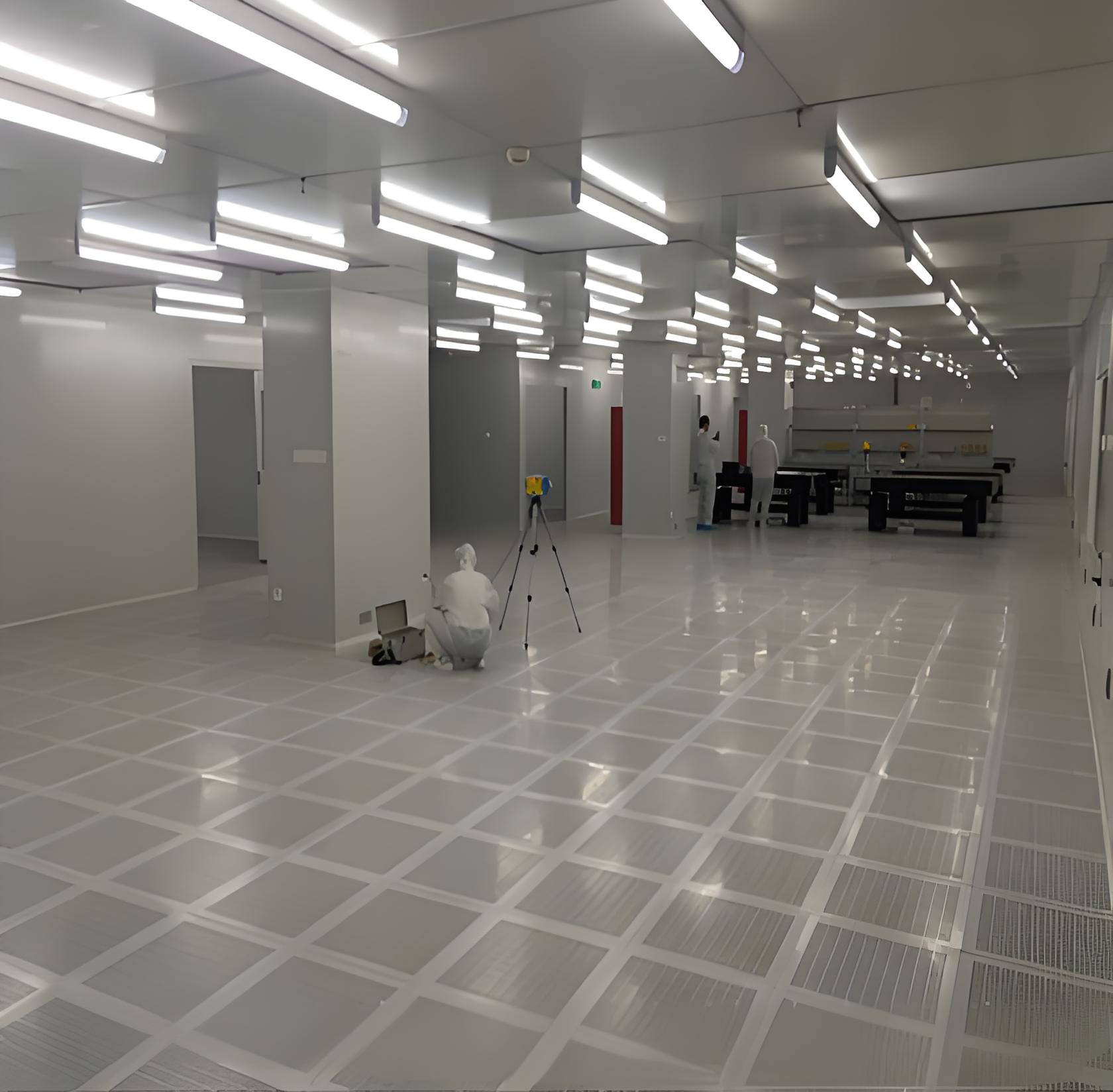
2. Architectural Layout and Zoning Strategies for Containment
Modern cleanroom design employs a graded pressure cascade system: the cleanest zone (e.g., filling room) maintains the highest positive pressure relative to adjacent corridors (Delta P ≥ 15 Pa for pharmaceutical, ≥ 10 Pa for electronics). The pressure differential is monitored via magnehelic gauges with alarm thresholds. Three zoning models dominate:
Ballroom (open plan): One large area with common HEPA filter coverage. Low construction cost but cross-contamination risk high; unsuitable for multi-product aseptic processing.
Stick-built segregated rooms: Individual small cells with separate air returns. Preferred for GMP Grade A/B as each room has independent parameters.
Modular hardwall system: Prefabricated panels with cam-lock connections. TAI JIE ER uses anodized aluminum framing and Class A fire-rated composite panels (mineral wool or honeycomb core). This approach reduces construction time by 40% and allows reconfiguration.
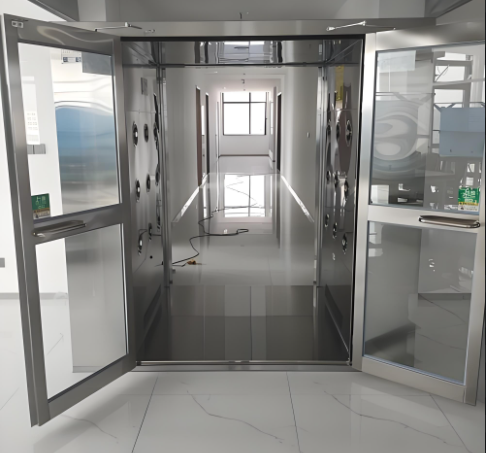
Additionally, the design must specify airlock types: cascade airlocks (high to low pressure), bubble airlocks (higher pressure on both sides for sterile barrier), or sink airlocks (lower pressure to contain contaminants). For potent compound handling, a pass-through chamber with interlocking doors is integrated into the cleanroom design to physically separate material transfer.
3. Material Specification for Surfaces, Seals & Utility Penetrations
Surface finish directly influences cleanability and particle retention. Acceptable materials include:
Modular wall panels: 50 mm thick sandwich panels with smooth PVC/PP skin, seamless edges, and integrated cam locks. Surface roughness Ra ≤ 0.8 µm.
Flooring systems: 100% solids epoxy with self-leveling, heat-welded seams. For electrostatic discharge (ESD) areas, carbon fiber or conductive quartz aggregates achieve 10⁶–10⁹ ohms.
Ceiling tiles: Gasketed, non-shedding aluminum honeycomb or powder-coated steel with gel-seal gaskets for leak-tight integration with fan filter units (FFUs).
Sealants: Neutral-cure silicone, fungicide-enhanced, with total outgassing ≤ 50 µg/g (ASTM C1246). For hydrogen peroxide resistance, use peroxide-cured fluorosilicone.
A critical but often overlooked element: utility penetration seals. Each pipe, conduit, or gas line passing through a cleanroom wall requires a validated split seal (Roxtec or equivalent) with compression modules that allow retrofitting. The engineering documentation must include penetration schedule with torque settings and pressure decay test records (≤ 0.5% leakage per hour at 200 Pa differential).
4. Air Filtration Hierarchy & Terminal Distribution Systems
Standard Cleanroom design includes three filtration stages: pre-filter (MERV 8), intermediate bag filter (MERV 14–15), and terminal HEPA (H13–H14 per EN 1822, or ULPA for ISO 4). Terminal filters can be arranged as:
FFU grid system: Multiple fan filter units mounted in a T-grid ceiling, each 1200×600 mm, independently speed-controlled. Provides redundancy and zonal control.
Ducted HEPA diffusers: Central AHU feeds ducts with laminar flow diffusers; better for high-ceiling industrial cleanrooms but requires more balancing valves.
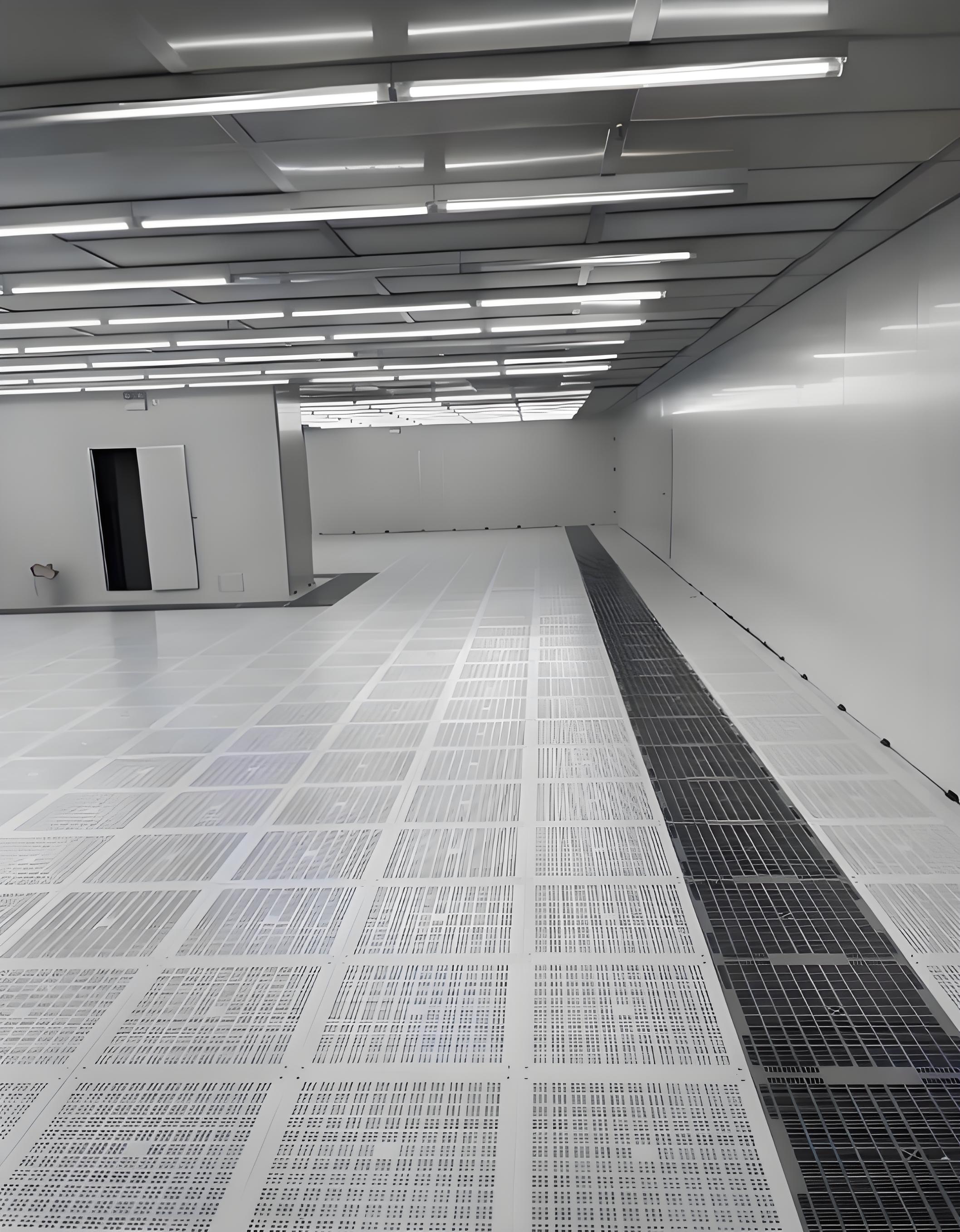
Low-velocity unidirectional ceiling: Full ceiling coverage with perforated plates below HEPA filters, achieving uniform downflow velocity within ±15% across the working plane.
For GMP Grade A (ISO 5) zones, the design must incorporate smoke pattern tests to visualize unidirectional airflow without dead zones. Recirculation pathways should locate returns at low-wall height (300 mm above floor) to minimize particle resuspension. TAI JIE ER integrates real-time particle monitoring systems with alarm integration into the BMS, allowing immediate detection of filter breakthrough or seal failures.
5. Process-Centric Design: Ergonomics, Equipment Integration & Material Flow
Contamination control is undermined if personnel movement or equipment layout violates cleanroom discipline. Key design principles include:
One-way material flow: Raw materials enter through a de-casing airlock, then pass through a pass-through, into processing, to finished goods exit – no backtracking.
Personnel flow separation: Separate gowning entrance for male/female with step-over benches, air showers (≥ 25 m/s jet velocity), and gowning room with progressive clean zones (gray to white to clean).
Equipment layout: Maintain at least 800 mm clearance behind equipment for cleaning; all machinery must be on stainless steel legs with coved floor seal; avoid horizontal surfaces where dust can accumulate.
A well-engineered cleanroom design also accounts for vibration isolation: semiconductor tools (steppers, inspection stations) require floor natural frequency > 10 Hz; use isolated inertia bases or active air springs.
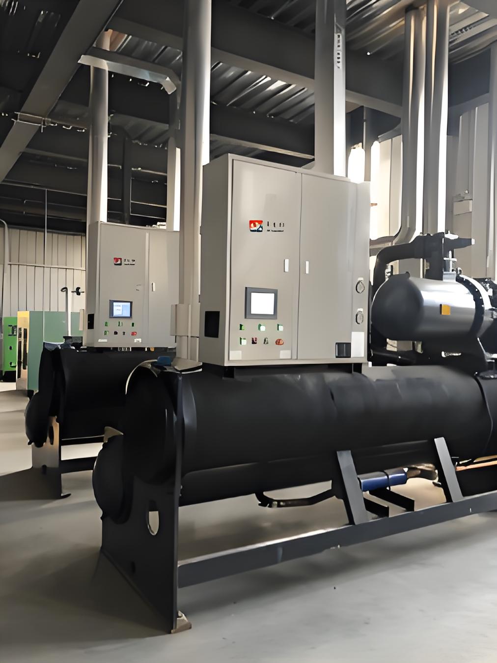
6. Energy Efficiency and Sustainable Design Elements
High air change rates and HEPA resistance lead to significant HVAC energy use (typically 40–50% of total facility power). Modern design mitigates this through:
EC plug fans (electronically commutated) in FFUs, reducing energy consumption by 30–40% compared to AC motors.
Demand-controlled ventilation: lower ACH during unoccupied shifts (night setback) with fast recovery (15 min) before operations.
Heat recovery wheels between exhaust and supply air streams (non-cross-contaminating type) for facilities requiring 100% once-through air.
Low-pressure-drop HEPA filters (initial ∆P ≤ 200 Pa) and optimized duct design to reduce fan static pressure.
Life-cycle cost analysis often favors slightly higher upfront investment in high-efficiency filters and EC fans, with payback periods of 2–3 years. TAI JIE ER provides energy modeling as part of the cleanroom design package, aligning with LEED v4.1 for industrial facilities.
7. Qualification and Validation Documentation for Design Handover
After construction, the design must be verified through DQ (design qualification), IQ (installation qualification), OQ (operational qualification). Essential tests include:
HEPA filter integrity (PAO aerosol challenge, maximum penetration 0.01% for H13).
Air velocity uniformity (grid measurement with 0.5 m spacing, coefficient of variation ≤ 15%).
Room pressure differentials (mapped with doors closed and open, minimum 10 Pa gradient).
Recovery test (from contamination generation to target class, per ISO 14644-3).
The final handover package must include cleanroom design drawings (showing filter positions, return air paths, pressure cascades), material certificates, sealant outgassing reports, and a full risk assessment (FMEA) for failure modes such as filter rupture or door interlock malfunction.
8. Frequently Asked Questions on Cleanroom Design
Q1: What is the difference between unidirectional and non-unidirectional airflow in cleanroom design?
A1: Unidirectional (laminar) flow uses parallel air streams moving at uniform velocity, typically from ceiling to floor, achieving ISO 5 or cleaner. Non-unidirectional (turbulent) flow uses dilution through air changes, suitable for ISO 6–9. Unidirectional requires full ceiling HEPA coverage and higher initial cost; turbulent is economical for lower classifications. The choice depends on process sensitivity to particle deposition.
Q2: How do you determine the required number of air changes per hour (ACH) for a new cleanroom?
A2: ACH is derived from ISO class target, internal particle generation rate (from personnel and equipment), and filter efficiency. A simplified method uses the formula: n = (G × 1000) / (C_target × V) where G = particle generation rate (particles/min), C_target = allowable particle concentration (particles/m³), V = room volume (m³). Typically, industry references (e.g., IEST RP-CC012.3) provide ACH baselines: ISO 5: 240–480 ACH (unidirectional), ISO 6: 150–240, ISO 7: 60–90, ISO 8: 15–30. For detailed design, CFD simulation is recommended.
Q3: What are common mistakes in cleanroom design that cause recurrent contamination?
A3: Frequent errors include: (1) placing returns on the same wall as air supply, creating short-circuiting; (2) insufficient pressure differential monitoring (missing alarms for door opening); (3) using unsealed utility penetrations; (4) selecting porous ceiling materials that cannot be washed; (5) ignoring ergonomics – overreaching personnel shed more particles; (6) forgetting to include gowning room HEPA coverage and air showers. A thorough design review with a specialist like TAI JIE ER prevents these issues.
Q4: Can modular cleanroom panels meet GMP Grade B requirements?
A4: Yes, provided panels have smooth non-porous surfaces (e.g., polypropylene or glass-reinforced plastic), seamless joints with compressed gaskets, and coved corners. Cam-lock modular systems can achieve air leakage ≤ 0.5 cfm/ft² at 150 Pa, which satisfies GMP Grade B. However, the room design must still guarantee ≥ 15 Pa pressure cascade to adjacent lower-grade areas. Many pharmaceutical projects use modular Cleanroom design due to faster validation.
Q5: What documentation should a cleanroom design consultant provide for regulatory audits?
A5: The consultant must deliver: (a) Design Qualification (DQ) protocol with user requirement specifications; (b) detailed CAD layout including airflow vectors, pressure zones, equipment coordinates; (c) material certification for all surfaces (non-shedding, chemical resistance); (d) HEPA filter placement and static pressure calculations; (e) risk assessment report (HACCP or FMEA); (f) commissioning plan (IQ/OQ templates). These documents are mandatory for FDA and EU GMP inspections.
Request an Engineering Consultation for Your Cleanroom Design Project
Every processing environment has distinct contamination challenges – from potent API handling to nano-scale semiconductor lithography. The controlled environment specialists at TAI JIE ER provide end-to-end Cleanroom design services: concept development, CFD simulation, material take-offs, construction management, and validation documentation. We deliver ISO 3 to ISO 8 facilities compliant with GMP Annex 1, ISO 14644, and FED-STD-209E (legacy).
Send your project inquiry including required ISO class, room area, target industry (pharma / biotech / electronics / medical devices), and any special process constraints (heat loads, solvents, vibration limits). Our technical team will prepare a preliminary design brief and budgetary proposal within 5 business days.
Contact methods: Use the official inquiry form on our website https://www.taijieer.com/contact.html or email directly to 912228126@qq.com. Include your company name, project location, and preferred technical call time.
Submit Design Inquiry → | Browse our portfolio of validated cleanrooms at www.taijieer.com


