Facility managers and process engineers responsible for sensitive manufacturing environments understand that a cleanroom is not simply a filtered room. It is a precisely engineered environment where airborne particle concentration, temperature, humidity, and pressure are controlled within defined limits. This article provides a technical examination of modern cleanroom design principles, including ISO 14644-1 classification, airflow architectures, material selection, and validation methodologies. Drawing from TAI JIE ER project data across pharmaceutical, semiconductor, and medical device industries, we address the engineering decisions that determine long-term compliance and operational reliability.

Any cleanroom operates under ISO 14644-1, which defines maximum allowable particle concentrations per cubic meter for particle sizes ≥0.1 µm up to ≥5 µm. For example, an ISO 5 cleanroom permits no more than 3,520 particles ≥0.5 µm per cubic meter, while ISO 7 allows 352,000 particles. These limits drive all downstream decisions: air change rates, filter coverage, and gowning protocols. Key performance parameters include:
Air changes per hour (ACH) – ISO 5 (unidirectional) typically requires 240–600 ACH; ISO 7 operates at 30–60 ACH; ISO 8 around 10–25 ACH.
Recovery time – the duration required to return to target cleanliness after a contamination event, measured in minutes.
Pressure differential – positive pressure (5–15 Pa) between the cleanroom and adjacent lower-grade areas prevents infiltration; negative pressure for containment of hazardous materials.
Air velocity – for unidirectional flow (laminar), velocities between 0.36 and 0.54 m/s are standard.
Modern modular cleanroom systems incorporate these metrics into computational fluid dynamics (CFD) models before construction. At a Korean semiconductor fab, implementing CFD-optimized return air grilles reduced dead zones by 78% compared to conventional diffuser layouts. The engineering phase must also account for heat load from process equipment – a common omission that leads to temperature excursions.
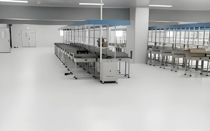
Selecting the correct airflow pattern is a primary decision when designing a cleanroom. Three configurations dominate industrial applications:
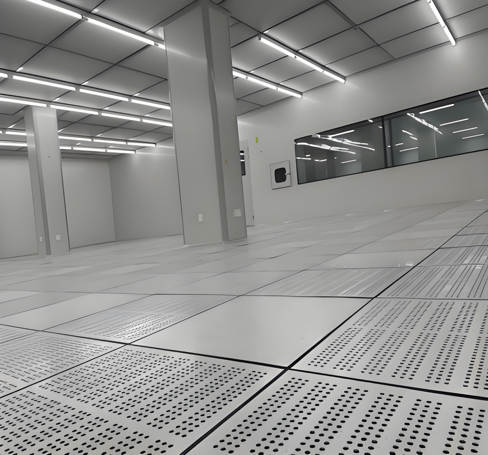
Unidirectional (laminar) flow – air moves in parallel streams from ceiling HEPA/ULPA filters to raised floor returns. Used for ISO 5 and stricter environments (pharmaceutical filling, semiconductor photolithography). Provides immediate particle sweep.
Non-unidirectional (turbulent) flow – air enters through distributed ceiling filters and returns through low-wall registers. Mixing dilutes contaminants. Suitable for ISO 6 to ISO 8 (medical device assembly, cosmetic manufacturing). Lower capital cost but requires higher ACH for equivalent cleanliness.
Mixed flow – unidirectional zones inside a turbulent background. Common in biopharma where filling heads require laminar protection while surrounding areas operate at ISO 7.
Each architecture imposes specific demands on fan filter unit (FFU) placement and return air pathways. For unidirectional rooms, raised access floors with perforated tiles are mandatory; non-unidirectional rooms can use low-wall returns. TAI JIE ER engineers conduct smoke visualization tests during commissioning to verify laminar integrity – a practice that often reveals unsealed cable penetrations or improper diffuser spacing.
Effective cleanroom operation identifies four contamination sources and implements layered controls:
Personnel (75–85% of particles) – Solutions: full-body coveralls (ISO 5), bunny suits, air showers (12–15 m/s jets for 15–30 seconds), sticky mats, and gowning rooms with step-over benches. Behavioral training reduces shedding by 60–70%.
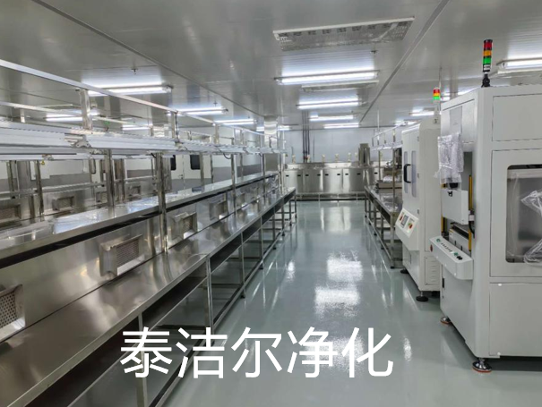
Equipment/process (10–15%) – Solutions: stainless steel surfaces with radius corners (no particle traps), vacuum extraction at process points, and local exhaust for powder handling.
HVAC system (5–10%) – Solutions: HEPA filters (99.97% at 0.3 µm) or ULPA (99.9995% at 0.12 µm), filter leak testing (PAO scan method), and humidity control (RH 40–60% to avoid electrostatic discharge).
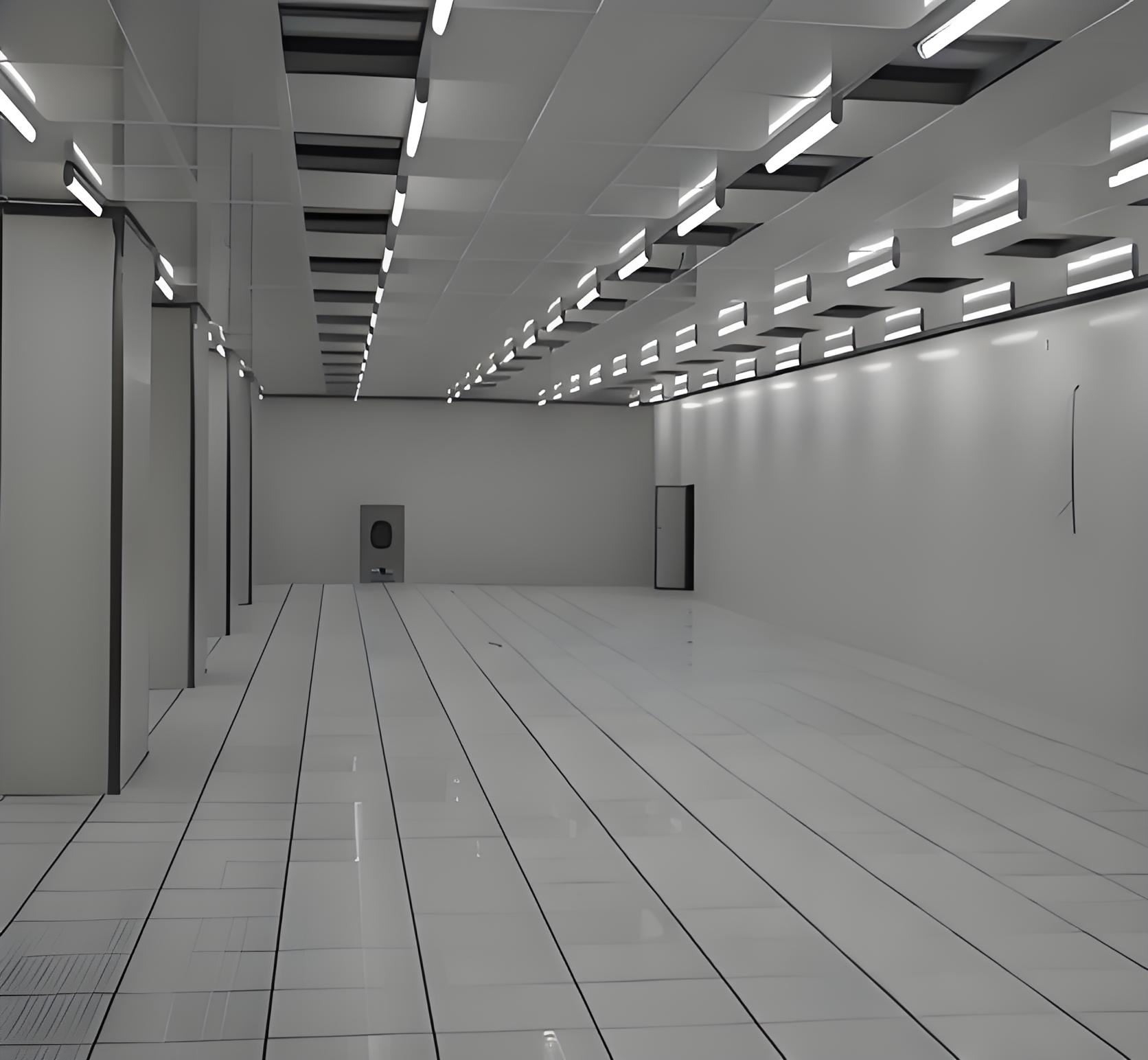
Building/facility (1–5%) – Solutions: seamless epoxy flooring, cove base transitions, non-shedding ceiling panels, and negative-pressure plenums for filter housings.
A pharmaceutical client reduced viable particle counts by 93% after TAI JIE ER redesigned the airlock sequence (changing from a single-door to a three-stage gowning with interlocked pass-through hatches). The retrofit also added particle counters at return air grilles for real-time alarming.
Challenge: Annex 1 (EU GMP) and FDA guidance require continuous monitoring of viable and non-viable particles at critical locations. Many older cleanrooms lack sufficient sensor density. Solution: deploy a distributed monitoring system with at least 2 sensors per filling needle. Data trending identifies filter degradation before action limits are exceeded. Pharmaceutical-grade cleanroom panels with smooth, crevice-free finishes facilitate cleaning and disinfectant compatibility testing.
Challenge: Nanoparticles (≤0.1 µm) and airborne molecular contaminants (AMC) – acids, bases, organics – damage photoresist and gate oxides. Solution: cleanroom design for AMC includes chemical filters (activated carbon, impregnated alumina) in the make-up air handler, plus mini-environments around wafer steppers. Vibration control (air spring isolators) is also mandatory for sub-10 nm nodes.
Challenge: ISO 7 or ISO 8 environments often have fluctuating personnel numbers, causing unstable particle loads. Solution: install a variable air volume (VAV) system that modulates FFU speed based on real-time particle counts and occupancy sensors. This approach reduced energy consumption by 34% in a catheter assembly line while maintaining ISO 7 at all times.
Proper cleanroom commissioning concludes with a rigorous test and certification phase per ISO 14644-2 and NEBB (National Environmental Balancing Bureau) standards. Required tests include:
Filter integrity (leak test) – photometer scanning of each HEPA/ULPA filter face and frame seal; acceptable leakage <0.01% of upstream challenge.
Air change rate measurement – using a calibrated vane anemometer or capture hood; must meet design ACH within ±10%.
Unidirectional velocity uniformity – for laminar rooms, 15–20 test points across the filter plane; maximum deviation ±20% from mean.
Pressure differential verification – all doors closed, measure between adjacent zones; minimum 5 Pa for pharmaceutical, 10 Pa recommended.
Particle count test – in operational state (dynamic) and at-rest; using ISO 14644-1 sampling protocol (number of locations = √area).
Recovery test – artificially introduce particles (e.g., with a nebulizer), then measure time to return to class limits; typically <20 minutes for ISO 7.
Documentation packages should include a traceable calibration certificate for all instruments. TAI JIE ER provides turnkey validation support, including protocol writing and on-site execution, which is particularly valuable for facilities undergoing regulatory inspection.
Cleanrooms consume 5–10 times more energy per square meter than commercial buildings, primarily due to high ACH and fan power. Modern engineering addresses this without compromising cleanliness:
EC plug fans – replace traditional belt-driven fans, offering 30–40% efficiency improvement and integrated speed control.
Demand-controlled filtration – reduce airflow during low-activity periods (nights, weekends) while maintaining positive pressure; validated by risk assessment.
Heat recovery wheels – capture exhaust air energy to precondition make-up air; requires careful selection to avoid cross-contamination.
LED lighting with motion sensors – reduces heat load, allowing lower cooling demand.
A medical device plant implementing these measures reduced annual cleanroom energy costs from $420,000 to $267,000 (36% reduction) while maintaining ISO 7 certification. Payback period was 1.7 years.
Based on post-occupancy evaluations of 50+ facilities, the following errors appear repeatedly:
Inadequate filter coverage – using 25% HEPA coverage in a non-unidirectional room but forgetting that low coverage creates stagnant zones. Minimum 35-40% coverage recommended for ISO 7.
Improper air return placement – returns located too close to particle-generating operations (e.g., vial capping) re-entraining contaminants. Return grilles should be positioned 1.5–2 m from major sources.
Overlooking door seals and pass-through boxes – gaps under doors or unsealed pass-through interlocks can nullify pressure differentials. Brush seals and interlocked transfer hatches are mandatory.
Insufficient gowning training – even an ISO 5 cleanroom will fail if operators don’t follow donning procedures. Video-based training and periodic glove/patch tests reduce human error.
A1: ISO 7 requires 30–60 air changes per hour and permits 352,000 particles (≥0.5 µm) per m³; ISO 8 requires 10–25 ACH and permits 3,520,000 particles. ISO 7 demands more robust HEPA coverage (35-40% of ceiling area) and typically uses unidirectional flow only in critical zones, whereas ISO 8 can operate with turbulent flow and 15-20% filter coverage. Pressure differentials for ISO 7 are usually 10-15 Pa to adjacent lower grades; ISO 8 may accept 5-10 Pa.
A2: Per ISO 14644-2, re-certification of classified cleanrooms should occur at maximum intervals of 12 months for particle count tests, filter integrity, and air change rate. However, pharmaceutical and semiconductor facilities often require 6-month intervals due to regulatory expectations (EU GMP Annex 1). In addition, any major modification (relocating a wall, adding equipment) triggers immediate re-testing.
A3: Yes, modern modular systems using pre-fabricated aluminum-framed panels with cam-lock connections achieve equivalent or better performance than traditional drywall or plaster construction. Modular systems offer superior flexibility for reconfiguration, shorter installation time (up to 50% faster), and comparable air-tightness (leakage <0.5% of volume per hour at 50 Pa). TAI JIE ER's modular cleanrooms have been certified to ISO 5 (Class 100) in aseptic filling applications.
A4: Wall surfaces should be smooth, non-porous, and resistant to cleaning agents. Common choices: polyurethane-coated steel panels (medical/pharma), fiberglass-reinforced plastic (FRP) for wet areas, or epoxy-painted aluminum. Flooring requires static-dissipative vinyl or seamless epoxy terrazzo (for heavy wheeled traffic). Coving (curved transitions between floor and wall) is mandatory in pharmaceutical cleanrooms to eliminate sharp corners where particles accumulate.
A5: First determine target ISO class → required air changes per hour (ACH). Then calculate room volume (m³) × ACH = total air supply volume (m³/h). Each HEPA filter (standard 610×610 mm) at 0.45 m/s delivers approximately 900 m³/h. Divide total supply by 900 to get number of filters. For ISO 7 (60 ACH, 100 m³ room): total supply = 6000 m³/h → 6.6 filters, so install 7 filters. Then confirm filter coverage ratio (filter area / ceiling area) – ISO 7 typically needs 35-40% coverage.
A6: An air shower is a self-contained chamber installed at the personnel or material entry point. It blasts high-velocity (20–25 m/s) HEPA-filtered air from multiple nozzles for 15–30 seconds, dislodging loosely attached particles from coveralls or packaging. Air showers reduce particle ingress by 80–95% and are mandatory for ISO 6 and stricter environments. However, they create a psychological barrier that reinforces gowning discipline.
Effective cleanroom design requires a holistic approach that balances ISO class requirements, airflow modeling, material compatibility, energy efficiency, and human factors. The difference between a compliant cleanroom and one that consistently passes inspections lies in attention to details: filter coverage maps, door interlock sequences, return air grille placement, and training program rigor.
For facility owners planning a new cleanroom or upgrading an existing one, TAI JIE ER offers full-spectrum services from conceptual design through commissioning and certification. Our engineers perform on-site particle mapping and CFD analysis to validate designs before construction begins.
Ready to discuss your cleanroom project? Send an inquiry to our engineering team – include your required ISO class, room dimensions, process description, and any regulatory standards (GMP, ISO, or FDA). We will respond with a preliminary design concept and budget estimate within 4 business days.
Submit your cleanroom project inquiry →


