
In the production of integrated circuits, flat panel displays, and advanced sensors, sub-micron contamination is not merely a quality defect—it directly determines fabrication yield and device reliability. Electronic purification engineering provides the systematic framework to identify, remove, and continuously suppress particulate, molecular, and electrostatic contaminants from controlled environments. This discipline combines cleanroom architecture, air filtration, gas-phase chemical removal, and real-time monitoring to achieve ISO Class 1–5 conditions. Below, we examine contamination sources, core purification technologies, and performance validation methods that define industry best practices.
Even in sealed cleanrooms, multiple vectors introduce unwanted species. Operators, equipment friction, raw material outgassing, and ambient air infiltration all contribute. To design effective purification strategies, engineers categorize contaminants into three families:
Airborne particles: Dust, skin flakes, tool wear debris, and fiber fragments. Sizes range from 0.1 µm to larger visible particles. In lithography steps, a single 0.2 µm particle on a wafer can destroy a die.
Airborne molecular contaminants (AMC): Acids (HF, HCl), bases (NH₃), condensable organics (siloxanes, phthalates), and doping agents (B, P compounds). AMC causes photo-resist poisoning, lens haze, and contact resistance drift.
Surface and electrostatic contamination: Ionic residues from improper handling, plus electrostatic discharge (ESD) that attracts particles and damages gate oxides.
Addressing these threats requires a layered approach. Passive barriers (gowning, air showers) reduce human-shed particles, but active electronic purification engineering integrates high-efficiency filtration, chemical adsorption, and airflow management to maintain stable cleanliness over years of operation.
Every ISO-compliant electronic cleanroom relies on core hardware and design rules. The following components form the backbone of contamination defense:
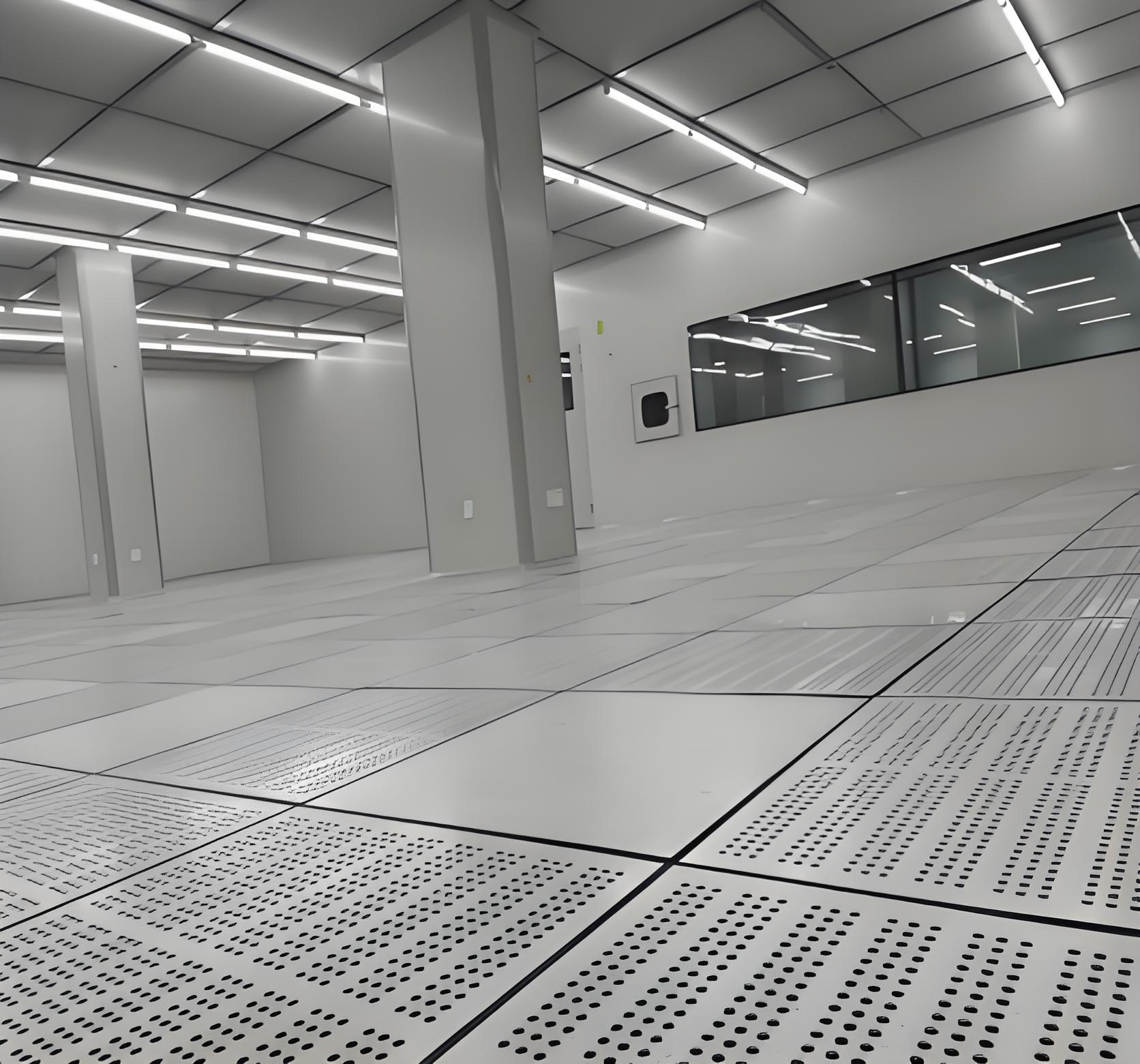
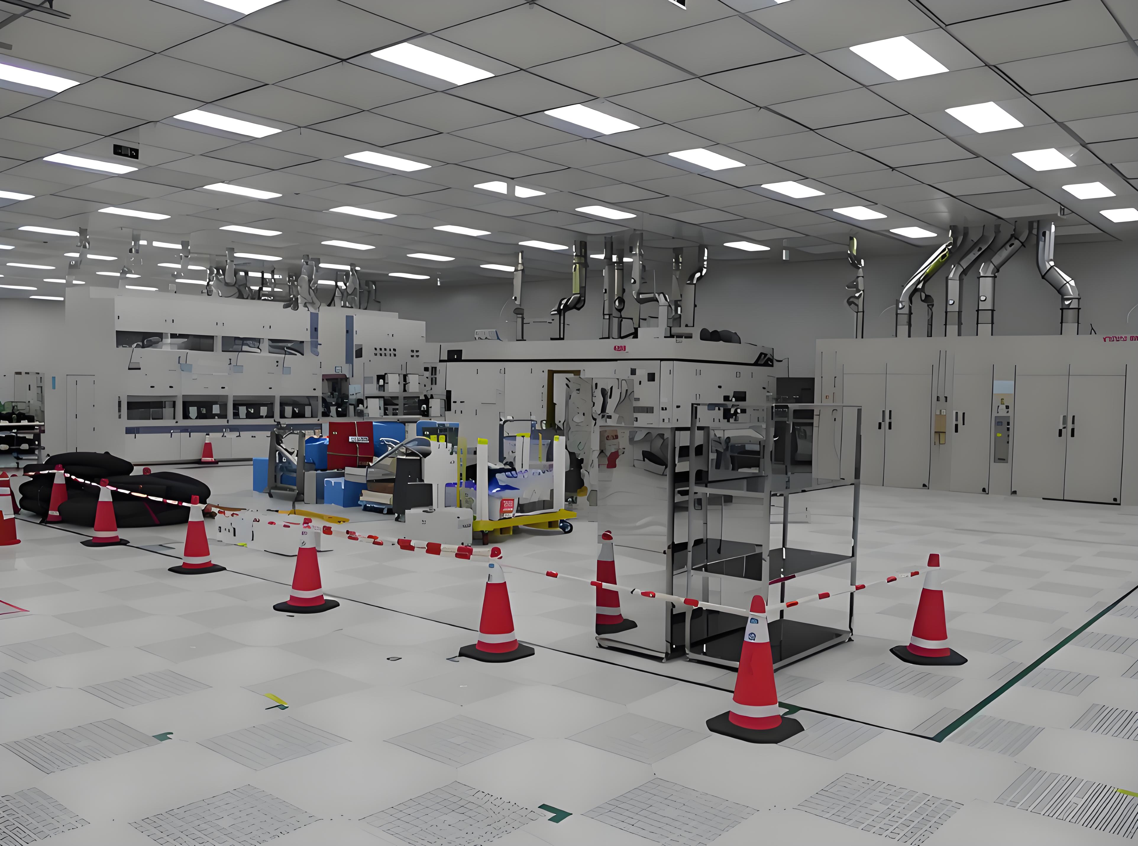
HEPA filters achieve ≥99.97% efficiency for 0.3 µm particles; ULPA filters extend to 99.9995% for 0.12 µm particles. In semiconductor front-end facilities, ULPA at point-of-use (just above the process tool) provides the highest local cleanliness. Fan filter units recirculate air through ceiling grids, achieving unidirectional (laminar) flow velocities of 0.3–0.5 m/s, which sweep particles downward to perforated raised floors.
ISO Class 5 cleanrooms typically require 240–600 air changes per hour. Positive pressure relative to adjacent zones (12.5–25 Pa) prevents infiltration from lower-class areas. For hazardous process zones (e.g., wet benches), negative pressure with scrubbers is used. Pressure differentials are monitored continuously; any drop triggers an alarm.
All cleanroom construction materials—wall panels, sealants, flooring, and conveyor belts—must have low outgassing. Volatile organic compounds (VOCs) from epoxy floors or silicone sealants can accumulate in recirculated air. Certified low-VOC materials and accelerated outgassing tests (e.g., SEMI S6, ASTM E595) are mandatory before installation.
For turnkey projects, TAI JIE ER provides integrated cleanroom packages that include FFU selection, HEPA certification, and pressure control logic, ensuring that the constructed environment meets specific fabrication requirements without costly retrofits.
Particle filtration alone cannot remove AMC. Gases pass through HEPA/ULPA media, then react on wafers or optical surfaces. Controlling AMC demands chemical filtration systems designed for the specific molecular profile of the fab.
Activated carbon impregnated with potassium permanganate: Oxidizes and traps aldehydes, H₂S, and SO₂.
Ion-exchange resin filters: Target acids (HF, HCl, HNO₃) and bases (NH₃) via chemisorption.
Zeolite and specialized sorbents: Remove organic dopants and organophosphates with high capacity.
Chemical filters are placed in make-up air handling units (MAUs) and recirculation FFU rows. Typical removal efficiency for target molecules reaches 90–99%, depending on face velocity and relative humidity. Periodic replacement intervals (every 6–18 months) are determined by on-site monitoring.
Real-time AMC detectors use ion mobility spectrometry (IMS) or cavity ring-down spectroscopy (CRDS) for specific gases (NH₃, HF). For broad-spectrum VOC monitoring, photo-ionization detectors (PID) and gas chromatograph-mass spectrometer (GC-MS) sampling provide lab-grade accuracy. Data log feed into facility control systems; when thresholds (e.g., 0.5 ppb for NH₃ in a DUV lithography area) are exceeded, automated alarms and increased filtration speed are triggered.
Modern electronic purification engineering shifts from standalone components to smart, networked contamination management. Key integration points include:
Distributed monitoring network: Laser particle counters (0.1 µm sensitivity) installed at return air plenums and near critical tools. AMC sensors located in make-up air ducts and return side.
Building automation system (BAS) integration: BAS reads pressure differentials, temperature (21–23°C ±0.5°C), humidity (40–50% RH ±2%), and filter load. Control loops adjust FFU speed and damper positions without operator intervention.
Energy-efficient purification design: Using low-pressure-drop ULPA media and variable frequency drives on FFU motors reduces energy consumption by up to 30% while maintaining ISO cleanliness. Demand-controlled filtration based on real-time particle counts saves operational expenses.
TAI JIE ER engineers deploy modular monitoring architectures that integrate seamlessly with existing SCADA systems. This approach gives fab managers a single dashboard for contamination KPIs, filter life remaining, and alarm histories—essential for predictive maintenance schedules.
Different electronic manufacturing segments impose unique demands on purification infrastructure. Below we analyze three representative scenarios:
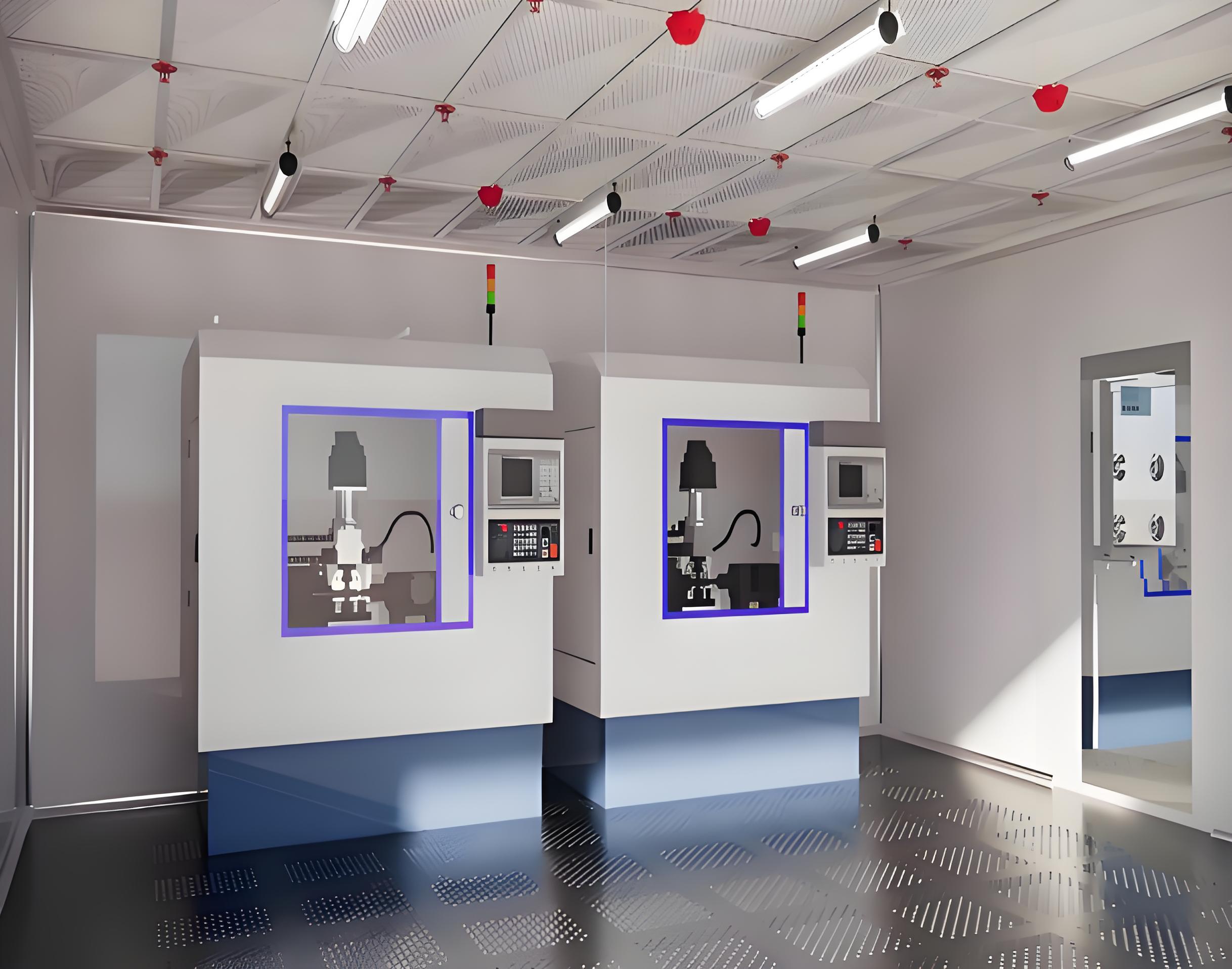
5 nm and 3 nm nodes require ISO Class 3 or even Class 2 environments for photolithography and etch modules. AMC limits are extremely tight: NH₃ ≤ 0.1 ppb, total acids ≤ 0.05 ppb, VOCs ≤ 0.2 ppb. Mini-environments (SMIF pods or EFEMs) with internal ULPA filters and purge ports isolate wafers from the ballroom air. Gas-phase filtration for process chemicals (e.g., 49% HF used in wet etching) demands dedicated exhaust scrubbers.
Generation 10.5 glass substrates (over 3 m × 3 m) generate high static charges and particle shedding from conveyance systems. Purification strategies emphasize air ionization bars above the glass path and laminar flow hoods covering deposition chambers. Large FFU arrays with 0.12 µm ULPA filters maintain ISO Class 5 across the entire ceiling grid.
PERC and TOPCon solar cells require lower cleanliness (ISO Class 6–7) for most steps, but diffusion and PECVD zones still need strict AMC control to prevent shunting. VOCs from screen-printed pastes and acids from texturing baths demand regional chemical filters and localized exhaust.
Each environment benefits from a tailored purification plan based on product sensitivity and throughput. Generic solutions often over-purify (wasting energy) or leave molecular contaminant hotspots. Professional electronic purification engineering matches filtration grade and air change rates to actual process risk.
Regulatory frameworks and industry standards provide measurable targets. The primary references include ISO 14644-1 (cleanroom classification by particle concentration), ISO 14644-2 (monitoring to demonstrate continued compliance), and SEMI F21-1102 (classification of AMC).
A typical validation protocol follows these stages:
Static testing: Before equipment installation, particle counters traverse the entire grid at working height. 99% of locations must meet specified ISO class.
Dynamic testing: With tools running and minimal operators, repeat particle and AMC measurements. Determine recovery time (time to return to class after a contamination event).
Periodic re-certification: Every 6–12 months or after any major facility modification. Sensor calibration and filter integrity tests (photometer scanning for HEPA leaks).
Non-compliance often traces to failing seals around filter frames, degraded chemical media, or pressure reversal due to door openings. Continuous monitoring dashboards flag such anomalies instantly, enabling corrective action before product is affected.
Q1: What differentiates electronic purification engineering from
standard HVAC filtration?
A1: Standard HVAC focuses on occupant
comfort and coarse dust removal (MERV 8–14). Electronic purification engineering
targets sub-micron particles (0.1–0.3 µm) and ppt-level molecular contaminants
using ULPA filters, chemical sorbent beds, and strict airflow unidirectionality.
Cleanrooms also enforce particle counting, gowning protocols, and static control
— none of which exist in ordinary HVAC.
Q2: How often should chemical filters be replaced in a semiconductor
fab?
A2: Replacement intervals vary from 6 to 24 months depending on
fab location (urban vs. rural), AMC load, and tool sensitivity. Fab managers
decide using break-through monitoring: when downstream AMC sensors detect a
concentration exceeding 30–50% of the limit, replacement is scheduled. Regular
quarterly sampling with GC-MS provides the data for predictive change-outs.
Q3: Can existing ISO Class 7 cleanrooms be upgraded to ISO Class 5 by
adding FFUs?
A3: Often yes, but a full engineering assessment is
required. Increasing FFU density raises air change rates, but the raised floor
open area, ceiling grid strength, and return air path must handle higher
airflow. Additionally, existing walls may leak particles at higher differential
pressures. A professional purification contractor will evaluate the current
construction before recommending FFU add-ons.
Q4: What is the role of air ionization in electronic purification
engineering?
A4: Air ionization neutralizes static charges that
attract airborne particles to wafer surfaces. Even with perfect filtration,
charged wafers will pull particles from the air. Pulsed DC ionizers (ceiling or
bar style) flood the environment with balanced positive/negative ions, reducing
electrostatic attraction. This complements filtration by preventing particle
deposition rather than only removing particles from air.
Q5: Do mini-environments (EFEMs) eliminate the need for a clean
ballroom?
A5: No. While load ports and EFEMs provide ISO Class 1–2
microclimates, operators and maintenance still access the ballroom. Contaminants
from the ballroom can enter through door seals or during wafer transfer. Thus
the ballroom must maintain at least ISO Class 5–6 to serve as a buffer.
Purification engineering optimizes both ballroom and mini-environment
simultaneously for maximum yield.
Every electronic manufacturing facility faces unique contaminants, throughput demands, and budget constraints. A standardized purification package rarely achieves the required yield without customization. Whether you are designing a new semiconductor fab, upgrading an existing photovoltaic line, or struggling with recurrent AMC-induced defects, expert guidance makes the difference.
Contact the purification engineering specialists at TAI JIE ER for a consultation. Their team provides feasibility studies, turnkey installation, and long-term monitoring contracts aligned with ISO 14644 and SEMI standards. Submit your inquiry via the website form or email to receive a preliminary contamination control roadmap for your project.
Send your cleanroom specifications or performance goals to TAI JIE ER's inquiry portal and receive a professional assessment within two business days.


