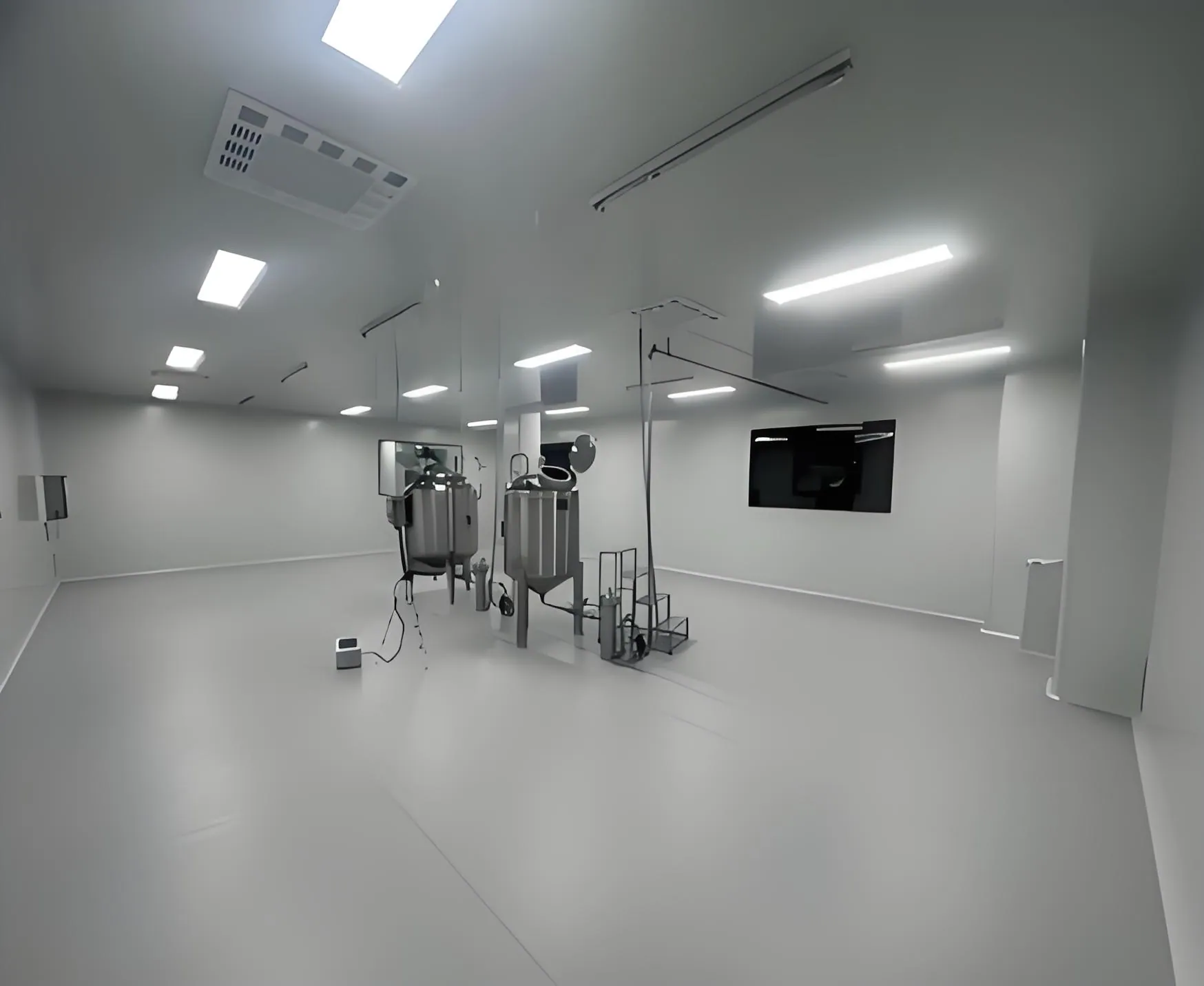
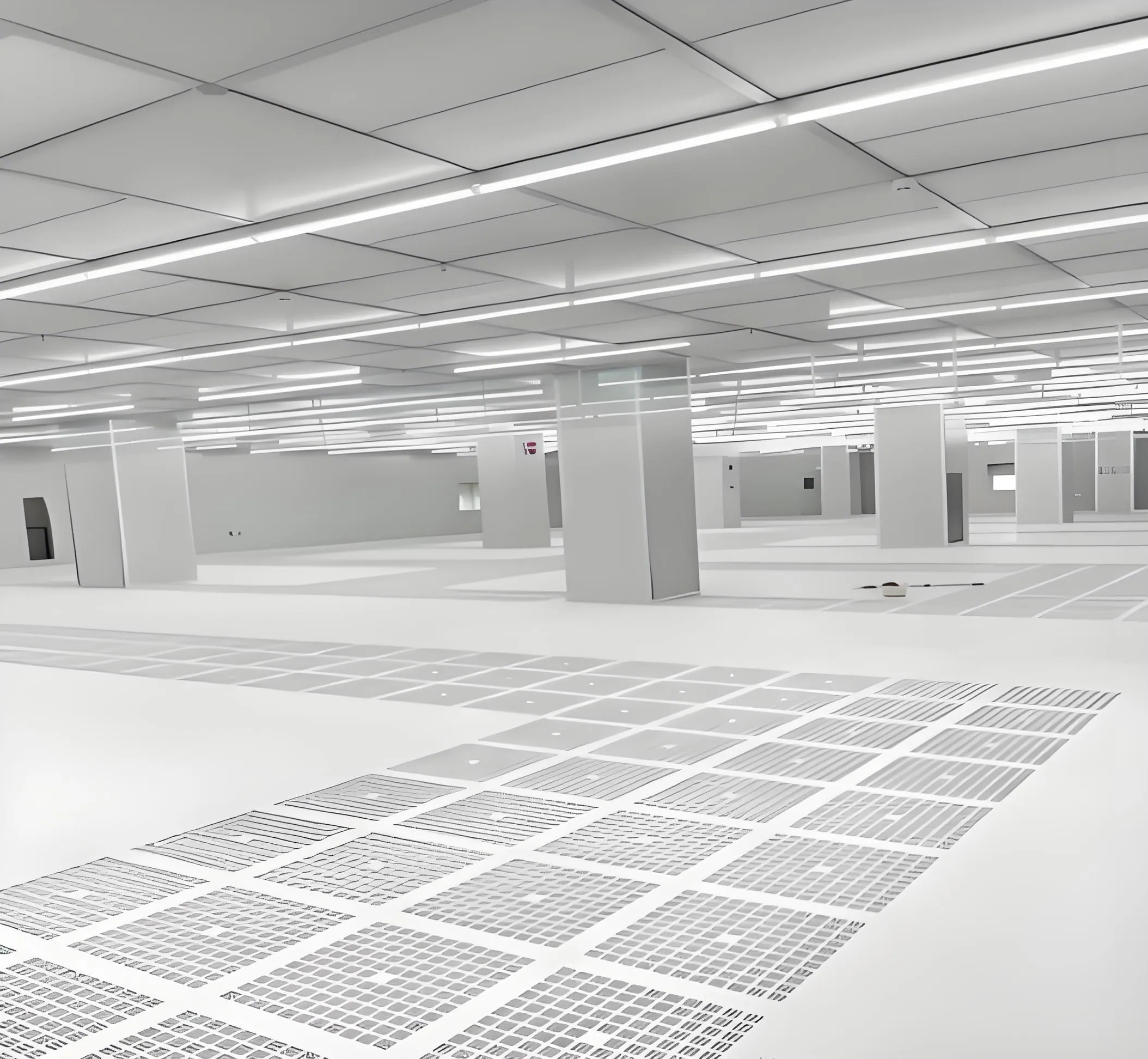
Modern high-technology manufacturing and sterile bioprocessing depend on microscopic environmental stability that conventional building systems cannot sustain. A single airborne particle measuring less than half a micron can bridge a circuit trace on an advanced microprocessor or introduce microbial contamination into an injectable biologic batch. Cleanroom Engineering addresses these vulnerabilities by integrating thermodynamics, aerodynamics, material science, and regulatory compliance into a unified physical envelope.
Designing a controlled environment requires far more than installing high-efficiency filters inside a sealed room. Facility planners must balance air change rates, psychrometric tolerances, static pressure differentials, structural vibration limits, and long-term operational energy demands. Every architectural joint, utility penetration, and air return path directly influences particulate dispersion and microbiological control across the lifecycle of the facility.
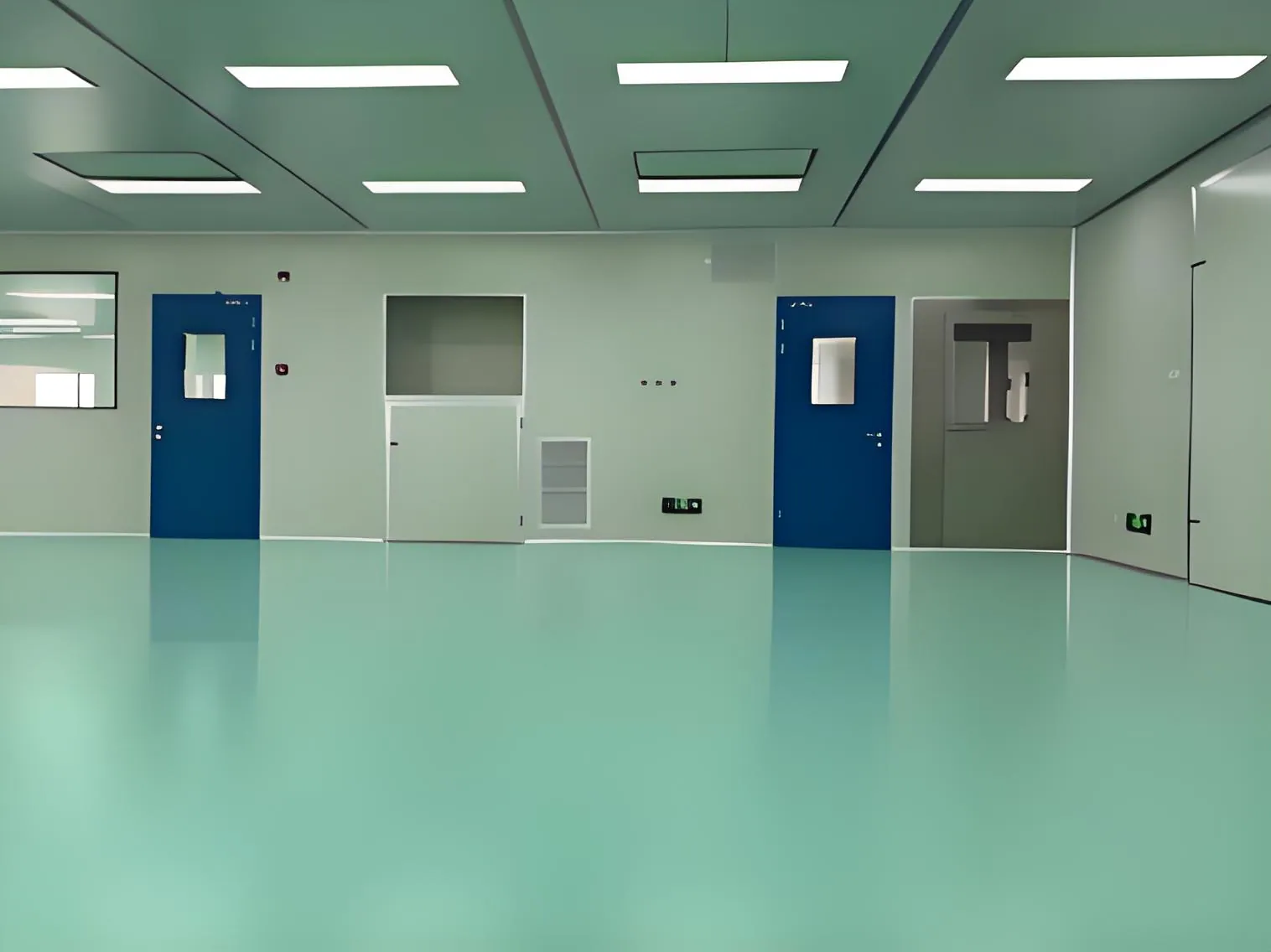
Global regulatory frameworks establish strict quantitative thresholds for airborne particulates, viable microorganisms, and molecular pollutants. Engineers establish design baselines by mapping process sensitivities against internationally recognized classification standards, primarily ISO 14644-1 and EU GMP Annex 1.
Under ISO 14644-1:2015, cleanrooms are categorized from ISO Class 1 through ISO Class 9 based on maximum allowable concentrations of non-viable particles ranging from 0.1 micrometers to 5.0 micrometers per cubic meter of air. For example, an ISO Class 5 environment permits no more than 3,520 particles measuring 0.5 micrometers or larger per cubic meter, whereas an ISO Class 7 space allows up to 352,000 particles of the same size threshold. Selecting the correct ISO class dictates every downstream mechanical parameter, including ceiling filter coverage and air velocity profiles.
Pharmaceutical and biotechnology operations operate under additional biological scrutiny defined by EU GMP Annex 1 and FDA cGMP guidelines. These regulations classify sterile zones into Grades A, B, C, and D, evaluating both non-viable particle counts and viable colony-forming units (CFUs) sampled through active air monitoring, settle plates, and surface contact plates. Regulatory auditors evaluate facilities under two distinct operational modes:
Beyond particulate matter, advanced microelectronics and optical fabrication facilities must govern Airborne Molecular Contamination (AMC) as outlined in ISO 14644-8. Volatile organic compounds (VOCs), acids, bases, condensable organics, and dopants can deposit onto wafer surfaces or corrode optical coatings, requiring specialized chemical scrubbing integrated directly into makeup air systems.
Maintaining certified classification thresholds depends on engineered air movement that continuously dilutes or sweeps contaminants away from critical process zones. Mechanical designers select between two primary airflow regimes depending on the target cleanliness grade and equipment layout.
High-grade environments from ISO Class 1 to ISO Class 5 rely on unidirectional (laminar) airflow. Air enters through full-coverage ceiling filter banks at a uniform velocity typically calibrated between 0.36 and 0.54 meters per second (70 to 100 feet per minute). This piston-like vertical movement drives particles generated by machinery or operators downward into perforated raised floors or low-wall return air chases before lateral dispersion can occur.
Moderate classifications ranging from ISO Class 6 through ISO Class 8 utilize non-unidirectional (turbulent mixing) airflow. Supply air enters through strategically spaced ceiling diffusers, creating controlled turbulence that dilutes airborne contaminants before exhausting them through low-level return grilles. Performance in turbulent zones is governed by Air Changes per Hour (ACH), typically spanning 20 to 40 ACH for ISO Class 8, 60 to 90 ACH for ISO Class 7, and 150 to 300 ACH for ISO Class 6 environments depending on internal heat loads and occupancy.
Particulate capture relies on terminal High-Efficiency Particulate Air (HEPA) and Ultra-Low Particulate Air (ULPA) filtration media constructed from pleated borosilicate micro-fiberglass. Filter performance is measured at the Most Penetrating Particle Size (MPPS), where diffusion and impaction capture mechanisms reach their lowest combined efficiency:
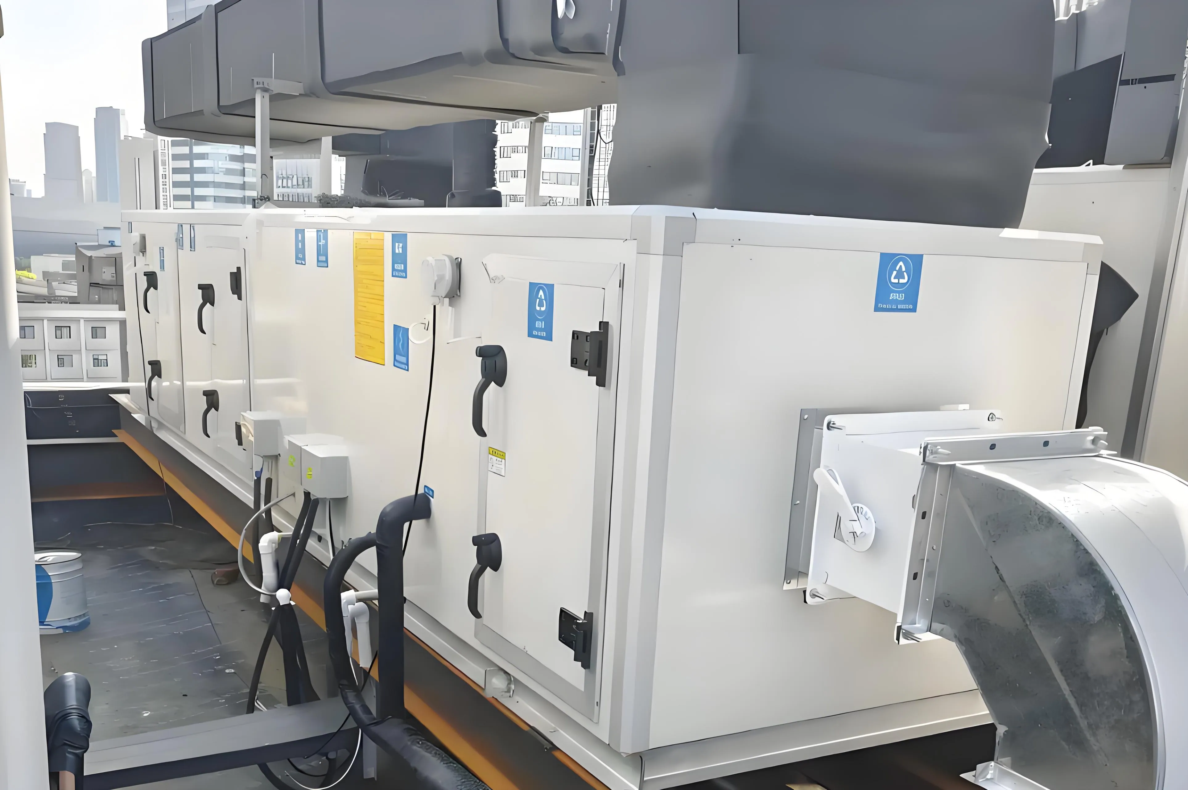
Mechanical engineers deploy these filters either through ducted terminal housings connected to central Air Handling Units (AHUs) or through modular Fan Filter Units (FFUs) mounted directly within a pressurized ceiling plenum. FFU configurations reduce large ductwork footprints and provide localized airflow balancing, while central AHU configurations simplify filter maintenance outside sensitive sterile cores.
Uncontrolled air migration through door undercuts, pass-throughs, and structural seams compromises environmental integrity. Cleanrooms prevent ingress or egress of contaminants through precise pressurization cascades, maintaining differential steps of 10 to 15 Pascals between adjacent zones of differing classifications. Sterile manufacturing and wafer fabs operate under positive pressure relative to external corridors to push clean air outward when doors open. Conversely, high-potency active pharmaceutical ingredient (HPAPI) suites and Biosafety Level 3 laboratories operate under negative pressure with dedicated exhaust scrubbers to contain hazardous aerosols inside the workspace.
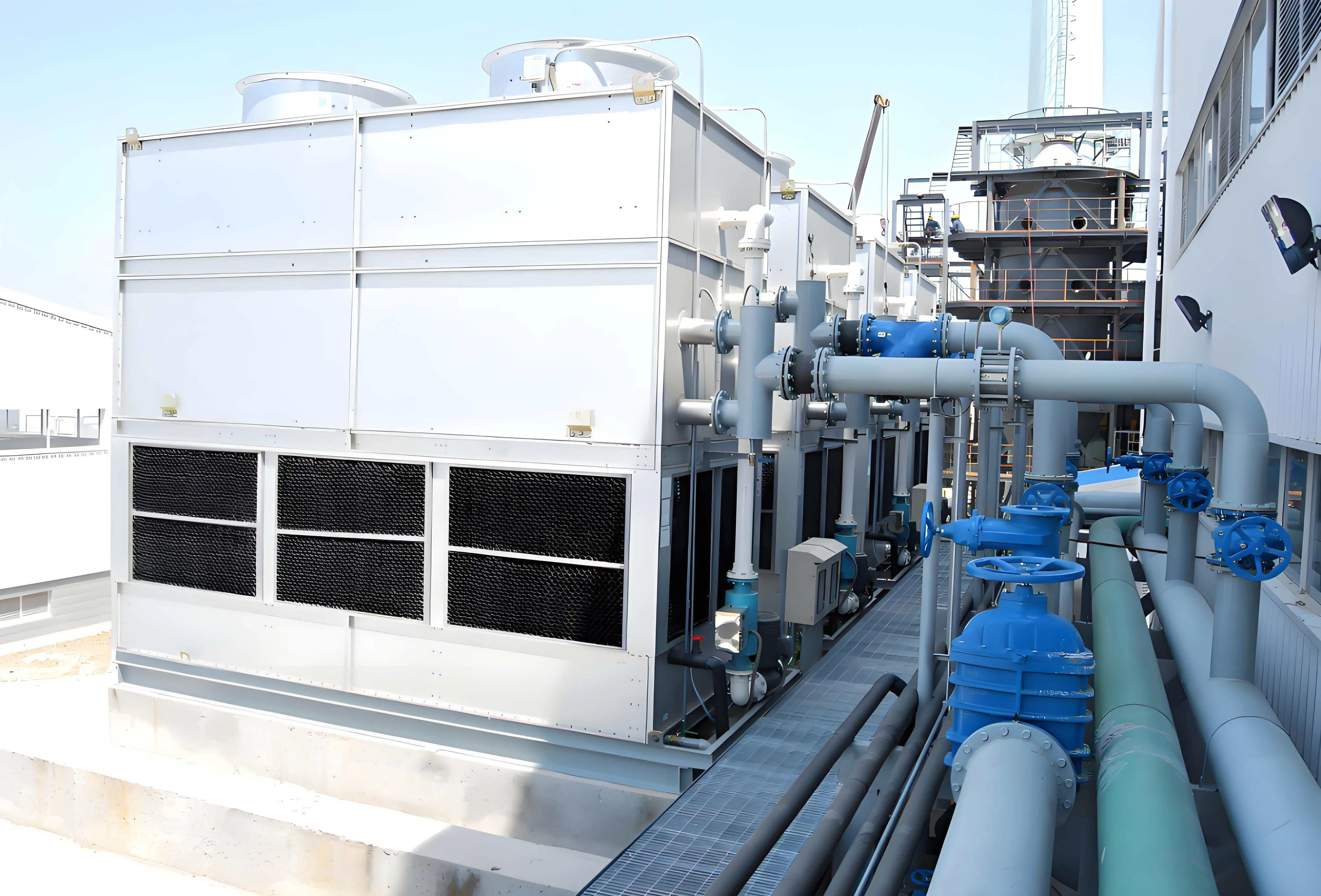
Thermal and humidity stability equally affect process yields and operator comfort. Excess humidity triggers microbial proliferation and moisture absorption in hygroscopic powders, whereas low relative humidity amplifies electrostatic discharge (ESD) events that destroy sensitive integrated circuits. Dual-stage chilled water coils paired with lithium chloride or silica gel desiccant dehumidification wheels maintain tight psychrometric envelopes, such as 20°C ± 0.5°C and 45% ± 2% relative humidity. To validate these dynamic interactions prior to procurement, TAI JIE ER applies Computational Fluid Dynamics (CFD) modeling to simulate airflow vectors, thermal plumes from process equipment, and potential eddy currents across complex room geometries.
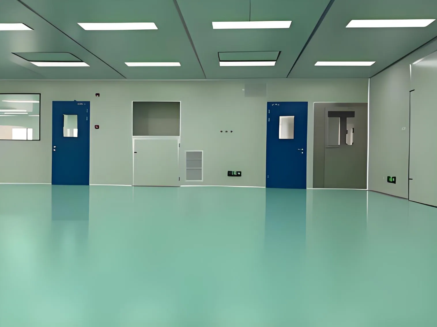
Mechanical performance fails when paired with porous, shedding, or improperly sealed interior surfaces. Architectural envelopes must form a monolithic, smooth, and chemically inert barrier capable of withstanding continuous pressure differentials and aggressive sanitation protocols.
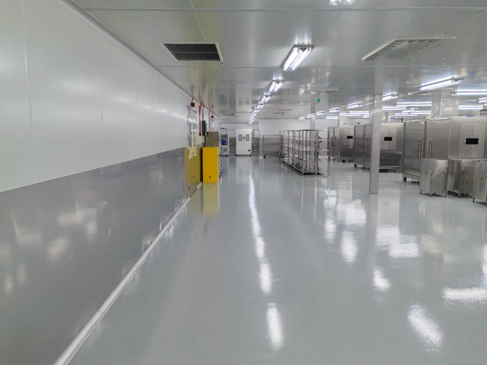
Wall and ceiling assemblies utilize prefabricated composite panels constructed with powder-coated galvanized steel, anodized aluminum, or 304/316L stainless steel skins bonded to non-combustible rockwool or aluminum honeycomb cores. In aseptic pharmaceutical facilities frequently fogged with Vaporized Hydrogen Peroxide (VHP) or wiped down with sporicidal agents, 316L stainless steel and high-pressure compact laminate panels resist oxidation and surface pitting. All panel-to-panel joints, wall-to-floor intersections, and wall-to-ceiling junctions integrate flush extruded aluminum coving sealed with non-outgassing, neutral-cure silicone or polyurethane sealants.
Flooring substrates must endure heavy rolling equipment loads while eliminating particulate entrapment and static buildup. Common specifications include:
Project delivery strategies increasingly favor off-site prefabrication over traditional stick-built drywall construction. Modern Cleanroom Engineering leverages Building Information Modeling (BIM) at LOD 400 to coordinate structural framing, flush LED lighting fixtures, fire suppression sprinklers, and high-purity utility drops before materials arrive on site. Modular panelized systems shorten installation schedules by 30% to 50%, minimize on-site construction dust, and permit future wall reconfigurations as manufacturing lines evolve.
Different regulated sectors impose conflicting physical demands on controlled environments, making standardized template designs ineffective for high-performance production lines.
Advanced wafer fabs face extreme sensitivity to sub-micron particulates, electromagnetic interference, structural micro-vibrations, and chemical outgassing. Extreme Ultraviolet (EUV) lithography equipment requires structural slabs engineered to Vibration Criterion curves VC-D or VC-E, isolating optical stages from nearby chiller compressors and vehicular traffic through deep foundation piles and isolated waffle slabs. Simultaneously, plasticizers and boron dopants leaching from standard construction adhesives can ruin silicon wafer yields. Engineers specify low-outgassing materials tested per ASTM E595 alongside point-of-use minienvironments—such as Standard Mechanical Interface (SMIF) pods and Front Opening Unified Pods (FOUPs)—to localize ISO Class 1 conditions directly around wafers while keeping surrounding ballroom spaces at ISO Class 5 or 6.
Sterile compounding, cell and gene therapy manufacturing, and vaccine fill-finish suites grapple primarily with cross-contamination during multi-product campaigns and microbial ingress from human operators. Personnel remain the largest source of viable contamination inside a cleanroom, shedding thousands of skin flakes per minute even inside full cleanroom garments. Solutions include replacing open human-operated Grade A laminar flow hoods with closed Isolators or Restricted Access Barrier Systems (RABS) equipped with glove ports and rapid transfer ports (RTPs). Furthermore, unidirectional personnel and material airlocks (PALs and MALs), combined with Clean-in-Place (CIP) and Steam-in-Place (SIP) utility loops for Water for Injection (WFI) and pure steam, maintain unbroken aseptic boundaries.
Engineering teams at TAI JIE ER address these sector-specific demands by integrating process utility piping, automated building management controls, and architectural containment into cohesive turnkey execution frameworks tailored to each facility's exact operational workflow.
Constructing a cleanroom represents only the initial phase of achieving operational readiness; rigorous empirical testing must verify that the built environment satisfies its engineering specifications under both static and dynamic conditions.
Regulated facilities follow a structured V-model validation lifecycle encompassing Design Qualification (DQ), Installation Qualification (IQ), Operational Qualification (OQ), and Performance Qualification (PQ). During OQ and PQ phases, certified testing specialists execute standardized measurements under ISO 14644-3 protocols:
Once qualified, operating a controlled environment demands substantial electrical power, often consuming 10 to 50 times more energy per square meter than a standard commercial office building due to continuous 24/7 fan operation and tight thermal conditioning. Forward-looking facility designs curtail lifecycle utility costs without compromising environmental compliance through Electronically Commutated (EC) motor FFUs, low-pressure-drop air handling coils, and enthalpy heat recovery wheels on exhaust airstreams. Automated Building Management Systems (BMS) paired with Environmental Monitoring Systems (EMS) also enable dynamic demand-controlled setbacks, safely reducing airflow velocities by 30% to 40% during verified unoccupied nighttime hours while preserving positive or negative differential pressure barriers.
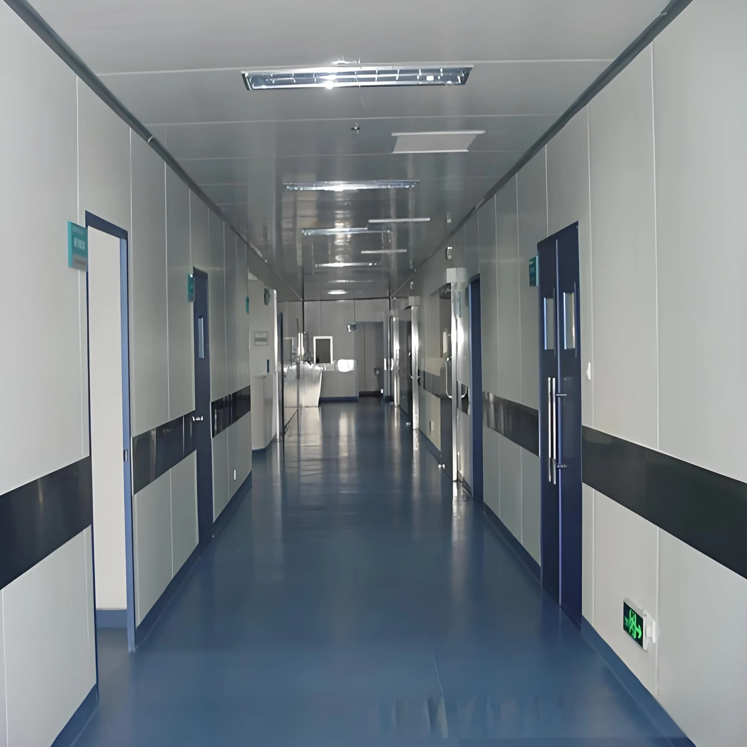
While both standards govern particulate limits, they measure different operational states and biological parameters. ISO Class 5 aligns broadly with EU GMP Grade A (in both at-rest and in-operation states) and Grade B (at-rest state) for particles at 0.5 micrometers and larger. ISO Class 7 aligns with EU GMP Grade B (in-operation) and Grade C (at-rest), whereas ISO Class 8 aligns with Grade C (in-operation) and Grade D (at-rest). EU GMP Annex 1 additionally mandates strict limits on 5.0-micrometer particles and viable CFU counts that ISO 14644-1 does not specify.
Target ACH cannot be selected from a generic table alone. Engineers calculate optimal ACH by evaluating the target ISO classification, internal heat gains from process machinery and lighting, internal particle generation rates from personnel and mechanical friction, room ceiling height, and desired room recovery times following door openings or maintenance events. High-heat semiconductor or autoclave zones often require higher ACH rates purely for thermal removal than particulate dilution alone would dictate.
Modular pre-engineered systems excel when project timelines are compressed, when existing warehouse shells must be retrofitted without disrupting adjacent operations, or when future process expansion is anticipated. Because wall panels, integrated air return chases, and ceiling grids arrive precision-cut from factory environments, modular Cleanroom Engineering minimizes on-site waste and simplifies validation. Conventional stick-built construction remains viable primarily for massive, permanent structural concrete cores requiring custom heavy load-bearing walls.
Energy reduction starts with minimizing static pressure losses across ductwork and filter media through generous duct sizing and low-face-velocity AHUs. Deploying variable-speed EC motors in FFUs significantly improves motor efficiency at partial loads compared to legacy AC induction motors. Additionally, installing real-time particle counters linked to the BMS allows facilities to modulate airflow downward during clean, unoccupied standby periods while maintaining continuous pressure differentials.
Performance Qualification verifies that the integrated facility functions consistently under actual production conditions with equipment running and gowned personnel executing standard operating procedures. PQ protocols include multi-day in-operation non-viable particle counting, active and passive viable microbial air and surface sampling, worst-case door opening recovery checks, temperature and humidity excursion mapping, and continuous differential pressure logging across shift changes.
Engineers utilize three distinct airlock architectures depending on whether the primary goal is product protection, operator containment, or both. Cascading airlocks step pressure progressively upward toward the clean core (e.g., Corridor 0 Pa, Airlock +15 Pa, Cleanroom +30 Pa). Bubble airlocks maintain higher pressure inside the airlock (+30 Pa) than both adjacent rooms (+15 Pa) to block cross-migration from either side. Sink airlocks maintain lower pressure inside the airlock (+5 Pa or negative) relative to both neighboring rooms (+15 Pa) to trap potent powders or biological agents inside the intermediate chamber.
Translating conceptual production targets into a validated, energy-efficient controlled facility requires coordinated mechanical, architectural, and regulatory expertise from day one. Early alignment between process equipment layouts, psychrometric loads, and ISO/GMP compliance targets eliminates costly field modifications during commissioning.
Partner with TAI JIE ER to translate your User Requirement Specifications (URS) into turnkey Cleanroom Engineering solutions tailored to your exact operational parameters. Engineering directors, procurement leads, and facility planners are invited to submit preliminary floor plans, target ISO or GMP classifications, room temperature and humidity tolerances, and process utility profiles to initiate a comprehensive technical evaluation and project quotation.